
Jetting, expansion and extrusion combined pile, construction method thereof and spiral jetting, expansion and extrusion drilling rig used in method

A construction method and technology of combined piles, which are used in earth-moving drilling, drilling equipment and methods, and drilling with mechanical conveying devices, etc. problems, to achieve the effect of saving concrete consumption, saving concrete consumption, and improving the bearing capacity of single piles

Active Publication Date: 2018-07-27
SHANDONG BEI TE LI FOUND ENG TECH CO LTD
View PDF12 Cites 8 Cited by
  • Summary
  • Abstract
  • Description
  • Claims
  • Application Information

AI Technical Summary

Problems solved by technology

[0006] However, since the diameter-expanding body is located at the extreme end of the pile body, that is, at the pile end, the scope of application of the combined pile is greatly limited.
Under complex geological conditions, such as when the bearing layer with high shear strength is located at a shallow depth, and the diameter expansion body of the composite pile is located at the pile end, the bearing capacity of the single pile cannot meet the design requirements

Method used


Image

  • Jetting, expansion and extrusion combined pile, construction method thereof and spiral jetting, expansion and extrusion drilling rig used in method
  • Jetting, expansion and extrusion combined pile, construction method thereof and spiral jetting, expansion and extrusion drilling rig used in method
  • Jetting, expansion and extrusion combined pile, construction method thereof and spiral jetting, expansion and extrusion drilling rig used in method

Examples


Embodiment 1

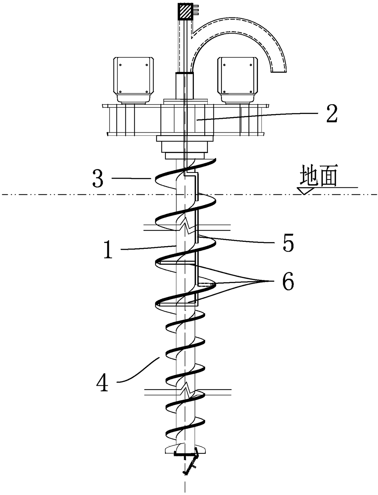
[0047] to combine Figure 1-2 As shown, a spiral spraying extrusion drilling rig includes a spiral hollow drill rod 1, a power head 2, and a high-pressure grouting pipe 5 is installed on one side of the outer wall of the core tube of the spiral hollow drill rod 1 from top to bottom, and the spiral hollow drill rod 1 It includes an upper drill rod 3 and a lower drill rod 4, wherein the upper drill rod 3 and the lower drill rod 4 are connected into one body through a flange, and the radius of the helical blade of the upper drill rod 3 is greater than the radius of the helical blade of the lower drill rod 4, so The lower end of the high-pressure grouting pipe 5 is provided with a multi-layer grouting nozzle 6, and each layer of the grouting nozzle 6 is located below the outer edge of the helical blade at the bottom of the upper drill pipe 3.

[0048] The length of the upper drill pipe 3 l 1 is 6m, and the length of the drill pipe 4 in the lower section is l 2 is 8m, the diamete...

Embodiment 2

[0053] As shown in Figure 3, a spray-expanded extrusion composite pile with high bearing capacity has a pile body consisting of a pile body 101, a diameter-expanding body 103 and a pile end 106. The pile body 101 is provided with a The expanding diameter body 103 of biconical frustum. A reinforcement cage is arranged in the pile body. The biconical frustum is a structure that is large in the middle and gradually becomes smaller up and down.

[0054] The diameter-expanding body 103 is located in the sand layer where the pile body 101 is located. The pile body 101 is provided with a layer of wing plates 102 that are substantially perpendicular to the axis of the pile body. Each layer of wing plates 102 has three pieces and is evenly distributed along the circumference. The width of the wing plate 102 is 5-25 cm, and the thickness is 2-12 cm.

[0055] The diameter of the pile body above the diameter expanding body 103 is greater than the diameter of the pile body below the diam...

Embodiment 3

[0065] Such as Figure 5 As shown, a spray-expanded extrusion composite pile with high bearing capacity is composed of a pile body 201, an expanding diameter body 203, a pile body 206, an expanding diameter body 208 and a pile end 211. The expanding diameter body 203 and the expanding diameter body The diameter body 208 is double-conical truncated, and is integrally formed with the pile body. A reinforcement cage is arranged in the pile body. The biconical frustum is a structure that is large in the middle and gradually becomes smaller up and down.

[0066] The diameter-expanding body 203 and the diameter-expanding body 208 are located at the position of the bearing layer with relatively high shear strength in the vertical direction of the pile body. The pile body 201 and the pile body 206 are respectively provided with a layer of wing plates (202, 207) substantially perpendicular to the axis of the pile body, and each layer of wing plates has three pieces, which are evenly ...


PUM


Abstract

The invention discloses a jetting, expansion and extrusion combined pile, a construction method thereof and a spiral jetting, expansion and extrusion drilling rig used in the method. A pile of the combined pile comprises a pile body, at least one expanded body and a pile end, and the at least one double-frustum-shaped expanded body integrally formed with the pile body is arranged on the pile body.Each expanded body is located in a vertical soil layer position, which has higher deformation modulus and shear strength, of the pile body, and at least two wing plates which are uniformly distributed in the circumference direction and basically perpendicular to the axis of the pile are arranged on the pile body. The diameter of the pile above the at least one expanded body is larger than or equal to that of the pile below the at least one expanded body. The drilling rig comprises an upper section and a lower section, the diameter of the upper section is larger than that of the lower section,and the at least one expanded body can be produced in any required position conveniently. When the at least one expanded body is located at the upper part or in the middle of the combined pile, if the diameter of the pile above the at least one expanded body is larger than that of the pile below the at least one expanded body, the consumption of concrete can be greatly reduced.

Description

technical field [0001] The present invention generally relates to concrete piles, and in particular relates to an on-site pouring concrete pile, a construction method and a drilling rig. Background technique [0002] At present, with the adjustment and development of the construction industry, construction projects have higher and higher requirements for foundation design and construction. Therefore, concrete piles are more and more widely used in construction projects such as high-rise buildings, bridges, high-speed rail, and ports. [0003] In order to make the pile foundation meet the requirements of anti-deformation, anti-seismic and architectural design of bearing capacity, methods such as lengthening the pile and increasing the diameter of the pile body are often used to increase the bearing capacity. However, lengthening or enlarging the pile body will lead to an increase in the amount of concrete, especially when the ratio of the length and diameter of the pile body ...

Claims


Application Information

Patent Timeline
Patent Type & Authority Applications(China)
IPC IPC(8): E02D5/36E21B7/00E21B7/28
CPCE21B7/005E21B7/28E02D5/36E02D15/04E02D2250/0023E02D2250/003E02D2300/002
Inventor 李金良
Owner SHANDONG BEI TE LI FOUND ENG TECH CO LTD
Learn More