Electric discharge weapon

a discharge weapon and electric technology, applied in the field of weapons, can solve the problems of soldier not having a non-lethal weapon ready, degenerating into a violent and dangerous mob,

Active Publication Date: 2006-12-05
AXON ENTERPRISE INC
View PDF7 Cites 38 Cited by
  • Summary
  • Abstract
  • Description
  • Claims
  • Application Information

AI Technical Summary

Problems solved by technology

For example, in many of today's “hot-spots” around the world, military units perform crowd control duties involving a crowd that is initially relatively peaceful but then degenerates into a violent and dangerous mob.
When confronted with a situation where non-lethal force may be more appropriate, the soldier may not have a non-lethal weapon ready.

Method used


Image

  • Electric discharge weapon
  • Electric discharge weapon
  • Electric discharge weapon

Examples


Embodiment Construction

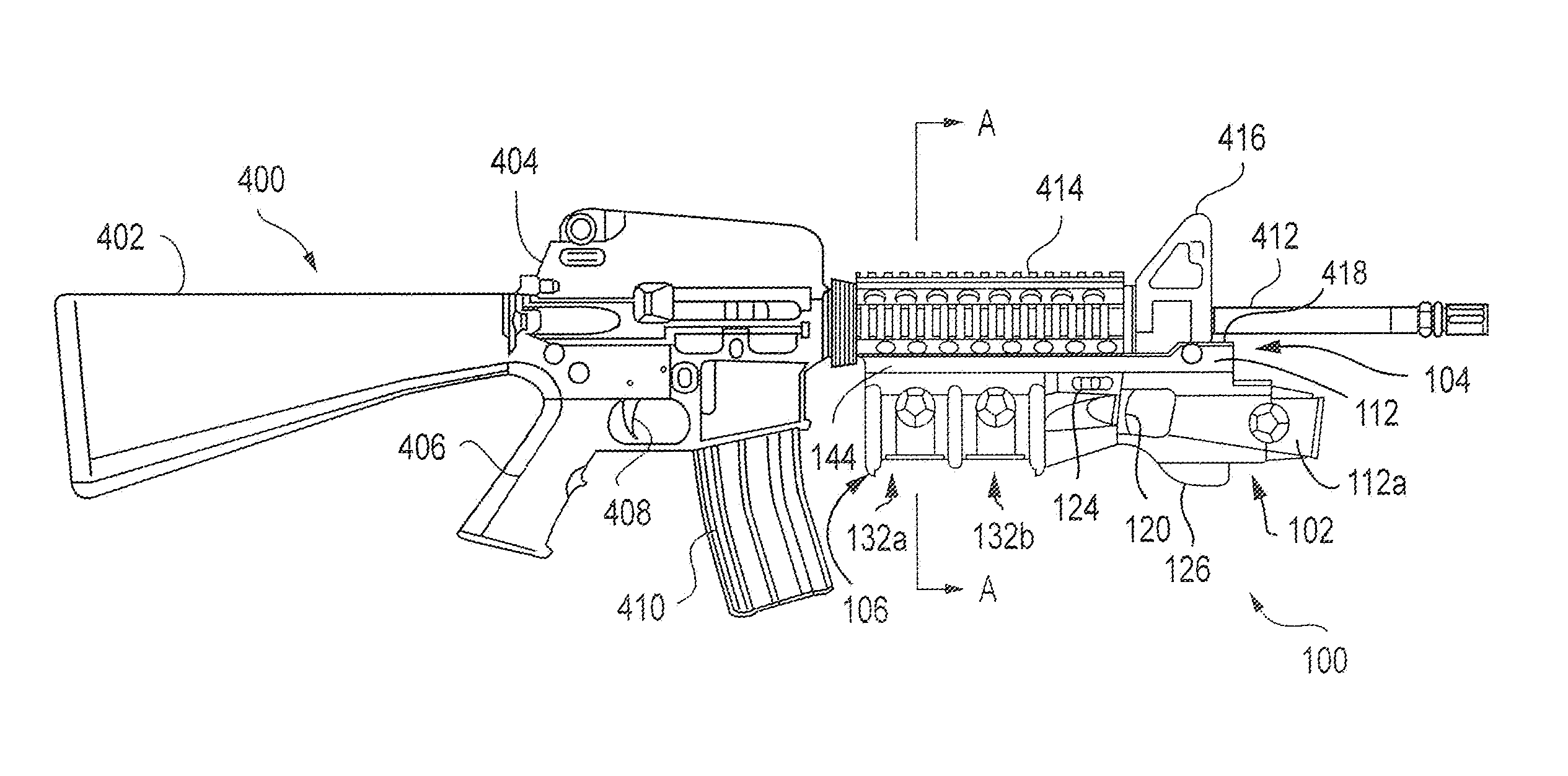
[0018]A multi-function weapon delivers force for offensive or defensive purposes. Force is delivered in multiple ways at the discretion of the operator. Force in each way may be lethal or non-lethal. In a first example, a conventional multi-function weapon may include a rifle with an attached chemical discharge device. Operation of the rifle (e.g., loading and firing) is largely independent of operation of the chemical discharge device that has its own mechanisms for loading and firing, though aiming of each may be in common. In a second example, a multi-function weapon may have multiple independent firing mechanisms. For example, a rifle may have an electric discharge weapon attached to it for common aiming. The rifle and electric discharge weapon may each have an independent means for loading and firing.

[0019]According to various aspects of the present invention, a conventional weapon or a conventional multi-function weapon may be used as a multi-function weapon system by attachin...


PUM


Abstract

A weapon, according to various aspects of the present invention, includes a receiver, a trigger, and a cartridge store. The receiver receives a cartridge. The cartridge applies a deterrent force to the target. The trigger activates the cartridge. The cartridge store stores a plurality of provided cartridges. The cartridge store, then the trigger, and then the receiver are arranged in sequence proceeding linearly away from a user of the weapon.

Description

FIELD OF THE INVENTION[0001]Embodiments of the present invention relate to weapons that apply force to incapacitate a target, for example, non-lethal force.BACKGROUND OF THE INVENTION[0002]Today's military and police encounter situations where application of both lethal and non-lethal force is desirable. For example, in many of today's “hot-spots” around the world, military units perform crowd control duties involving a crowd that is initially relatively peaceful but then degenerates into a violent and dangerous mob. In such situations, a soldier may need a way to subdue violent elements in the crowd using non-lethal force while retaining a means for applying lethal force in order to further protect himself if the crowd becomes violent and dangerous. In these situations, soldiers typically hold one weapon at a time, the weapon of choice being some sort of lethal force weapon such as a rifle. When confronted with a situation where non-lethal force may be more appropriate, the soldier...

Claims


Application Information

Patent Timeline
Patent Type & Authority Patents(United States)
IPC IPC(8): F41B15/04
CPCF41A19/58F41G1/35F41H13/0012
Inventor CEROVIC, MILANDUBAY, DAVID
Owner AXON ENTERPRISE INC
Why Eureka
Try Eureka