Internal combustion engine and combustion control method

a combustion engine and control method technology, applied in the direction of electric control, machines/engines, spark plugs, etc., can solve the problems of low degree of freedom of combustion control, large portion of radicals disappearing, and no easy existence, so as to reduce the effect of introducing radicals, and limit the amount of radicals produced

Inactive Publication Date: 2007-11-22
NISSAN MOTOR CO LTD
View PDF6 Cites 40 Cited by
  • Summary
  • Abstract
  • Description
  • Claims
  • Application Information

AI Technical Summary

Benefits of technology

[0007]It has been discovered that with the engine disclosed in Japanese Laid-Open Patent Publication No. 2001-323829, since an ozone generating device is provided at the intake port in order to set an angle against combustion start timing, the degree of freedom of the combustion control is low because the control can only be executed during the intake stroke. Furthermore, it is known that radicals, e.g., ozone (O3), hydroxyl radical (OH), and other active oxygens, do no easily exist at low temperatures, and thus, a large portion of the radicals disappear between the time when they are introduced during the intake stroke and the time when the ignition timing is reached. Consequently, the effect of introducing the radicals is diminished. Meanwhile, with the engine disclosed in Japanese Laid-Open Patent Publication No. 200

Problems solved by technology

It has been discovered that with the engine disclosed in Japanese Laid-Open Patent Publication No. 2001-323829, since an ozone generating device is provided at the intake port in order to set an angle against combustion start timing, the degree of freedom of the combustion control is low because the control can only be executed during the intake stroke.
Furthermore, it is known that radicals, e.g., ozone (O3), hydroxyl radical (OH), and other active oxygens, do no easily exist at low temperatures, and thus, a large portion of the radicals disappear between the time when they are introduced during the intake stroke and the time when the ignition timing is reached.
Meanwhile, with the engine disclosed in Japanese Laid-Open Patent Publication No. 2001-020842, since the electric discharg

Method used


Image

  • Internal combustion engine and combustion control method
  • Internal combustion engine and combustion control method
  • Internal combustion engine and combustion control method

Examples


Embodiment Construction

[0026]Selected embodiments of the present invention will now be explained with reference to the drawings. It will be apparent to those skilled in the art from this disclosure that the following descriptions of the embodiments of the present invention are provided for illustration only and not for the purpose of limiting the invention as defined by the appended claims and their equivalents.

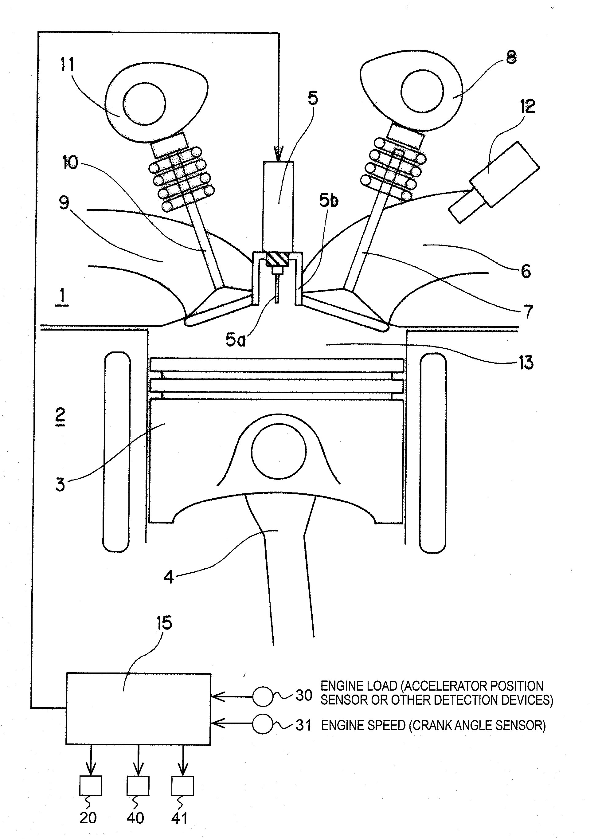
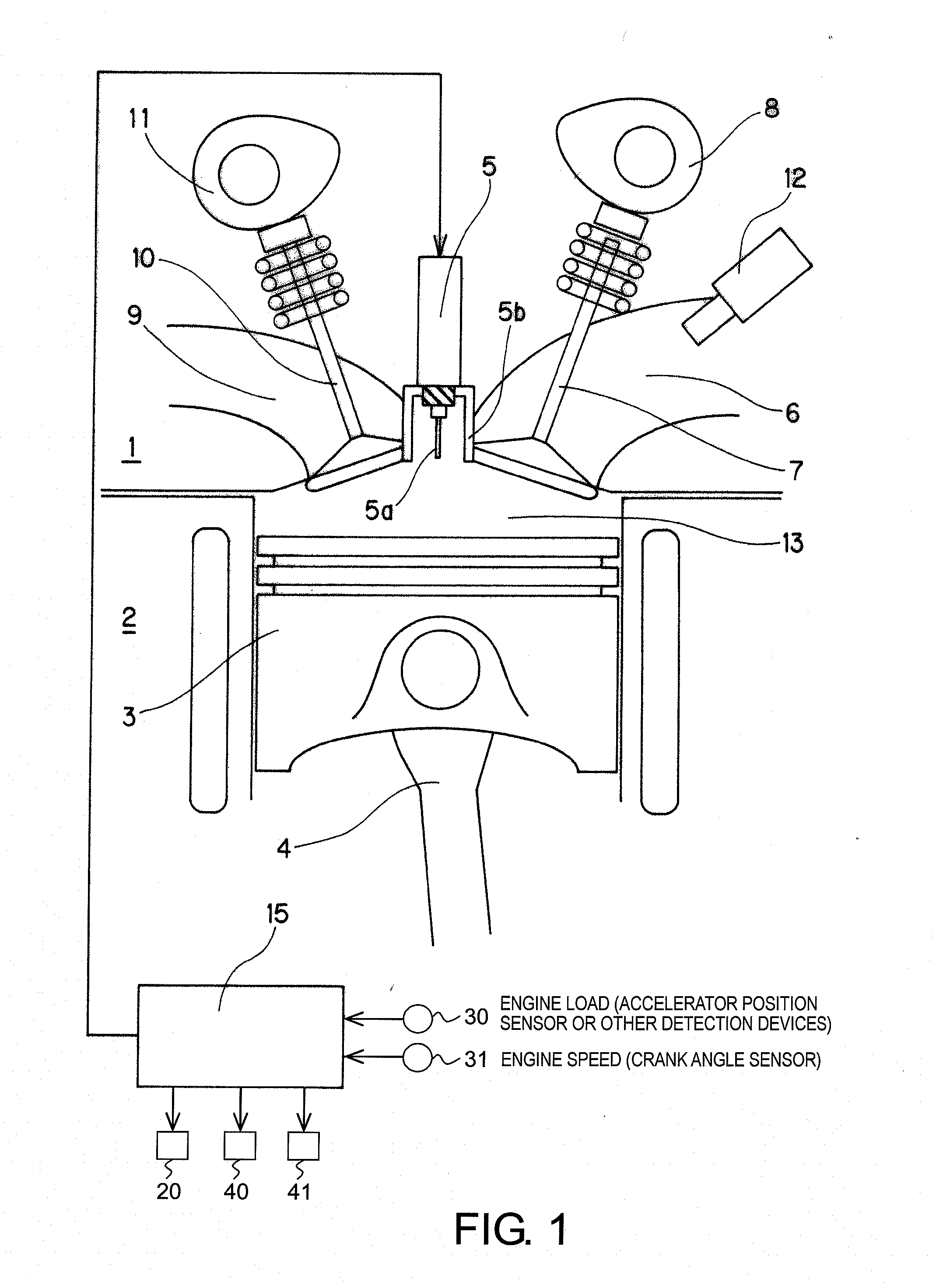
[0027]Referring initially to FIG. 1, an internal combustion engine is schematically illustrated in accordance with a first embodiment of the present invention. As shown in FIG. 1, the engine is a gasoline engine that includes a cylinder head 1 and a cylinder block 2. While only a single cylinder is illustrated, it will be apparent to those skilled in the art from this disclosure that the engine preferably includes multiple cylinders, with each cylinder including a piston 3, a connecting rod 4, an electric discharge unit 5, an intake port 6, a pair of intake valves 7 (only one shown in FIG. 1), an i...


PUM


Abstract

An internal combustion engine is provided that basically comprises a combustion chamber, an electric discharge unit and a controller. The combustion chamber receives a mixture of fuel and air that is caused to undergo compression self ignition. The electric discharge unit is provided inside the combustion chamber to generate an electric discharge for conducting combustion inside the combustion chamber. The controller is configured to control a voltage applied to the electric discharge unit. The controller is configured to control the electric discharge unit such that a non-thermal plasma can be formed without incurring a transition to arc discharging, and to control the quantity and distribution of an activated air-fuel mixture inside the combustion chamber in accordance with an operating condition of the internal combustion engine.

Description

CROSS-REFERENCE TO RELATED APPLICATIONS[0001]This application claims priority to Japanese Patent Application No. 2006-137483, filed on May 17, 2006. The entire disclosure of Japanese Patent Application No. 2006-137483 is hereby incorporated herein by reference.BACKGROUND OF THE INVENTION[0002]1. Field of the Invention[0003]The present invention relates to an internal combustion engine configured to ignite a premixed air-fuel mixture introduced into a cylinder by compression self ignition. The present invention also relates to a combustion control device for such an engine.[0004]2. Background Information[0005]Japanese Laid-Open Patent Publication No. 7-71279 discloses an example of an internal combustion engine configured to ignite a premixed air-fuel mixture introduced into a cylinder by compression self ignition. An advantage of igniting a premixed air-fuel mixture by compression self ignition is that combustion reactions start substantially simultaneously in a plurality of places ...

Claims


Application Information

Patent Timeline
IPC IPC(8): F02B19/00H01T13/20F02P23/00
CPCF02D41/3041Y02T10/128F02P23/04Y02T10/12
Inventor NAGAMINE, MORIHIROKAKUHO, AKIHIKOSHIRAISHI, TAISUKETAKAHASHI, EIJI
Owner NISSAN MOTOR CO LTD
Why Eureka
Try Eureka