Accelerator position sensor

a position sensor and accelerator technology, applied in the direction of converting sensor output electrically/magnetically, cycle control systems, cycle equipment, etc., can solve the problems of low design freedom with respect to detection angle and operating load in accelerator position sensors, and the inability to individually change the operating load of the driver, etc., to achieve the effect of increasing the degree of design freedom

Active Publication Date: 2022-01-20
TOYO DENSO
View PDF0 Cites 0 Cited by
  • Summary
  • Abstract
  • Description
  • Claims
  • Application Information

AI Technical Summary

Benefits of technology

[0007]Accordingly, an object of the present invention is to solve the abovementioned problem that the degree of freedom in design with respect to a detection angle and an operating load in an accelerator position sensor is low.
[0010]With the configurations as described above, the present invention enables increase of the degree of freedom in design with respect to a detection angle and an operating load in an accelerator position sensor installed in a throttle grip.

Problems solved by technology

However, in the abovementioned magnet, the magnetized states of the magnetic poles at the end and on the side face of the magnet are the same, so that the fully open angle of the throttle grip and the operating load on the driver cannot be changed individually.
As a result, there arises a problem that the degree of freedom in design with respect to a detection angle and an operating load in an accelerator position sensor is low.

Method used


Image

  • Accelerator position sensor
  • Accelerator position sensor
  • Accelerator position sensor

Examples


first example embodiment

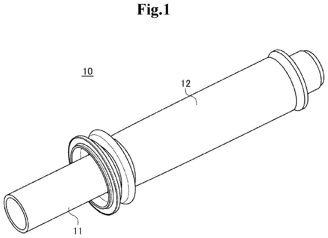
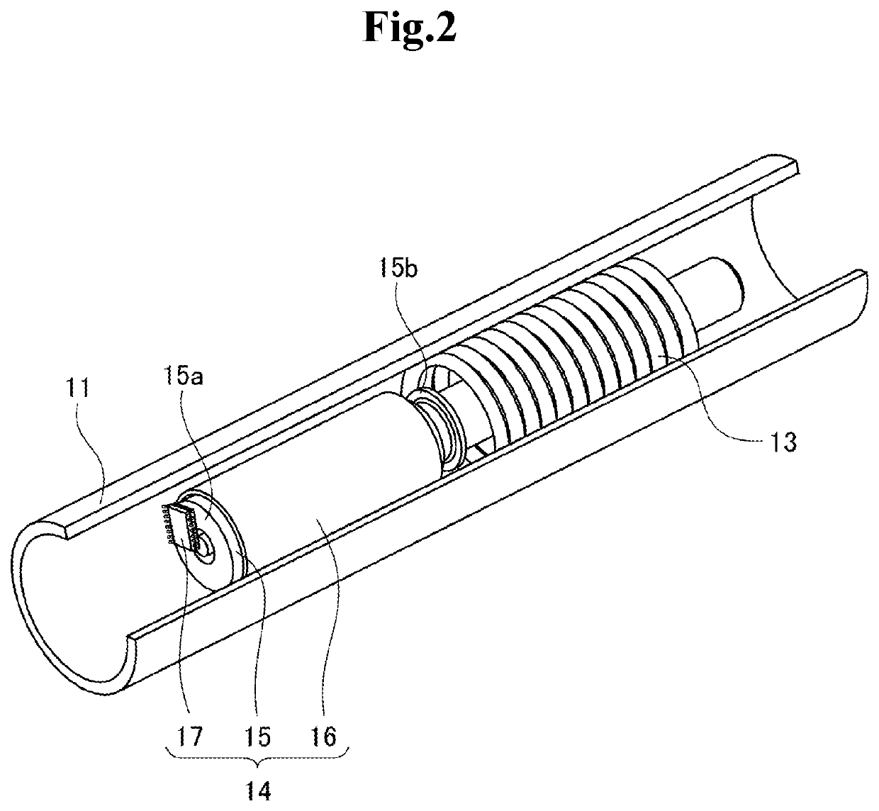
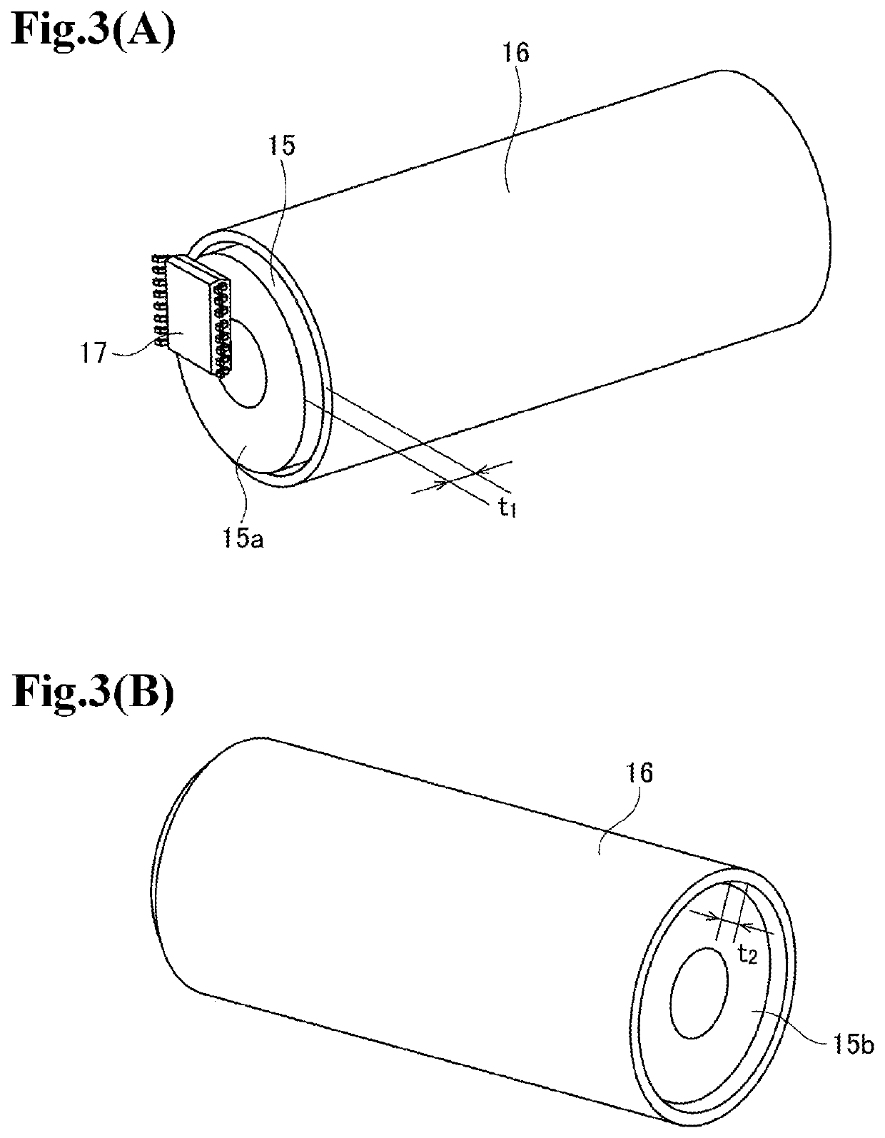
[0021]A first example embodiment of the present invention will be described with reference to FIGS. 1 to 7. FIG. 1 is a view for describing the configuration of a throttle device, and FIGS. 2 to 7 are views for describing the configuration of an accelerator position sensor.

[Configuration]

[0022]An accelerator position sensor 14 in this example embodiment is a device for detecting the degree of rotation of a rotating body, that is, the rotation position (the position) in the rotation direction of the rotating body. Specifically, the accelerator position sensor 14 in this example embodiment is mounted on a throttle device 10 for operating an accelerator of a motorcycle as shown in FIG. 1, and is for detecting the rotation angle of a throttle grip 12. Moreover, the accelerator position sensor 14 in this example embodiment is for generating a feeling of operation due to a resistance force against a rotation operation of the throttle grip 12 by a driver. However, the accelerator position ...


PUM


Abstract

An accelerator position sensor according to the present invention is held inside a throttle grip of a vehicle rotationally operated by a driver. The accelerator position sensor includes: a magnet extended along a rotation axis of the throttle grip and configured to rotate in conjunction with the throttle grip; a magnetic detection unit arranged so as to face a predetermined face of the magnet; and a magnetic body arranged so as to face another face that is different from the predetermined face of the magnet. On the predetermined face and the other face of the magnet, respectively, mutually different numbers of magnetic poles are magnetized along a rotation direction of the magnet.

Description

INCORPORATION BY REFERENCE[0001]This application is based upon and claims the benefit of priority from Japanese patent application No. 2020-122235, filed on Jul. 16, 2020, the disclosure of which is incorporated herein in its entirety by reference.TECHNICAL FIELD[0002]The present invention relates to an accelerator position sensor installed in a throttle grip of a vehicle.BACKGROUND ART[0003]On a motorcycle, a driver rotates a throttle grip and thereby adjusts an accelerator opening to operate an accelerator. Detection of an accelerator opening is performed by detection of the rotation angle of a throttle grip. Meanwhile, in recent years, detection of an accelerator opening is often performed by detection of a magnetic flux generated by a magnet rotating together with a throttle grip by a magnetic sensor.[0004]Patent Document 1 discloses an example of an accelerator position sensor that detects an accelerator opening with a magnetic sensor. To be specific, the accelerator position s...

Claims


Application Information

Patent Timeline
Patent Type & Authority Applications(United States)
IPC IPC(8): G01D5/14B62J45/413
CPCG01D5/14B62J45/413B62J45/422B62K23/04
Inventor KISHI, SHOJIYOSHIDA, TOSHIYAOTANI, TAKAYUKI
Owner TOYO DENSO
Why Eureka
Try Eureka