Light source device and projector

a light source and projector technology, applied in the direction of electric variable regulation, process and machine control, instruments, etc., can solve the problems of low temperature of the electrodes arc cannot be stabilized, front end of the electrode, etc., to suppress flickering, improve the durability of the high-pressure discharge lamp, and improve the durability of the projector

Inactive Publication Date: 2008-01-31
SEIKO EPSON CORP
View PDF2 Cites 39 Cited by
  • Summary
  • Abstract
  • Description
  • Claims
  • Application Information

AI Technical Summary

Benefits of technology

[0012]An advantage of some aspects of the invention is to provide a light source device and a projector which are capable of improving the durability of a high-pressure discharge lamp and suppressing flickering.

Problems solved by technology

However, in this type of lighting / driving of the high-pressure discharge lamp, the temperatures of the electrodes of the high-pressure discharge lamp become relatively low and, although the first protrusion is formed, the position of the arc is moved and thus the arc cannot be stabilized, and accordingly, there is a problem of so-called flickering.
In other words, in the technology disclosed in JP-A-2001-2440838, a low-frequency rectangular waveform current having a relatively high frequency and a high-frequency rectangular waveform current are supplied to the high-pressure discharge lamp and the front end of the electrode becomes worn, and accordingly the durability of the high-pressure discharge lamp cannot be improved.
On the other hand, the generation of an arc is limited to only one of the several spots on the surfaces of the same electrodes in the negative electrode phase.

Method used


Image

  • Light source device and projector
  • Light source device and projector
  • Light source device and projector

Examples


first embodiment

[0039]Hereinafter, a first embodiment of the present invention will be described with reference to accompanying drawings.

Schematic Configuration of Projector

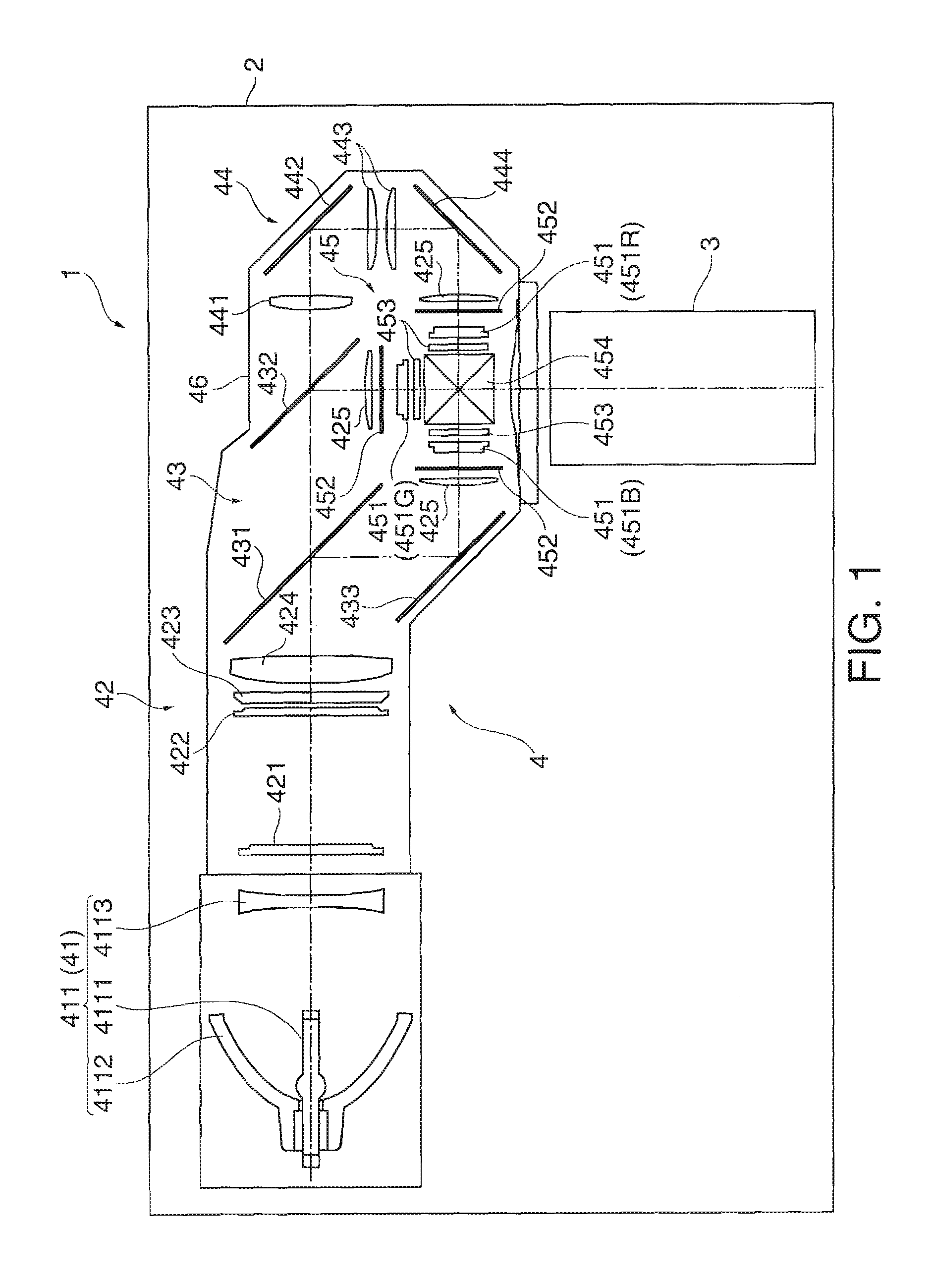
[0040]FIG. 1 is a diagram showing a schematic configuration of a projector 1.

[0041]The projector 1 modulates a light beam emitted from a light source in accordance with image information to form a color image (optical image) and projects the color image on a screen (not shown in the figure) on an enlarged scale. The projector 1, as shown in FIG. 1, includes an external case 2 in the form of an about rectangular parallelepiped, a projection lens 3 as a projection optical device, and an optical unit 4.

[0042]In FIG. 1, although detailed drawing is omitted, a refrigeration unit which refrigerates the inside of the projector 1, a power unit which supplies electric power to constituent members inside the projector 1, a control substrate which controls the configuration members inside the projector 1, and the like are disposed in a spa...

second embodiment

[0088]Next, a second embodiment of the invention will be described with reference to the accompanying drawings.

[0089]Hereinafter, to a same structure or member as that in the first embodiment, a same reference sign is attached and detailed description thereof is omitted or simplified.

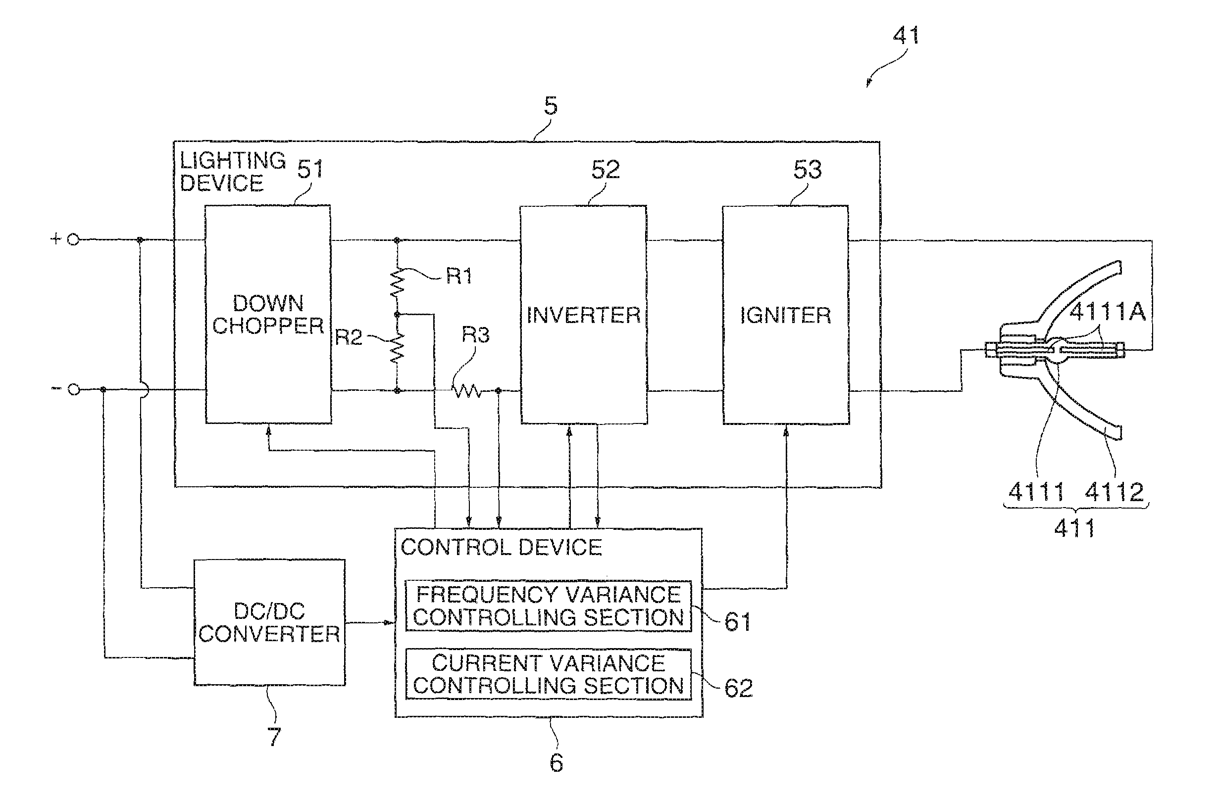
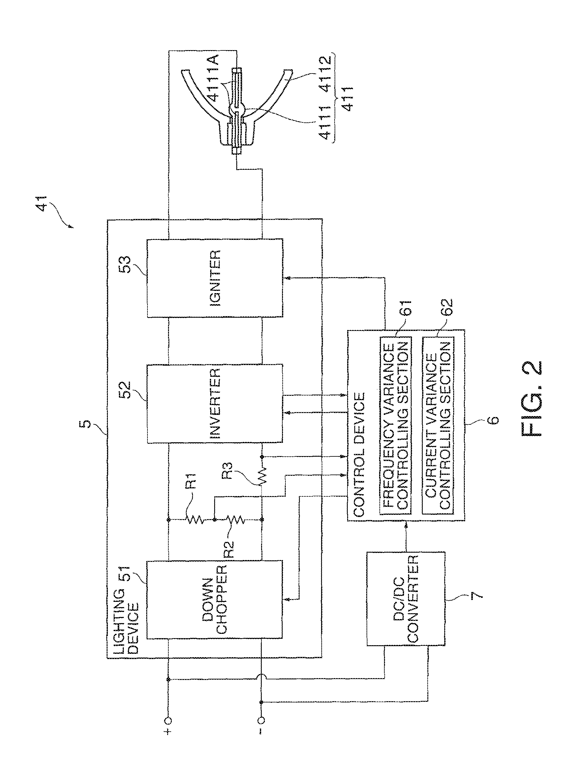
[0090]In the first embodiment, the frequency variance controlling section 61 supplies driving currents of the low frequency, the first high-frequency, and the second high-frequency to the light source lamp 4111 respectively at time intervals T1, T2 and T3 in performing the frequency variance control.

[0091]On the other hand, in the second embodiment, the frequency variance controlling section 61 supplies the first high-frequency driving current and the second high-frequency driving current to the light source lamp 4111 right before the polarity inversion of a waveform of the low frequency driving current at each half period of the waveform of the low frequency driving current in performing the frequency ...


PUM

PropertyMeasurementUnit
frequencyaaaaaaaaaa
frequencyaaaaaaaaaa
frequencyaaaaaaaaaa

Abstract

A light source device includes a high-pressure discharge lamp for performing electric discharge emission between a pair of electrodes, a lighting device for lighting the high-pressure discharge lamp by supplying a driving current of a predetermined frequency to the high-pressure discharge lamp, and a control device for controlling the lighting device, wherein the control device controls the frequency of the driving current supplied to the high-pressure discharge lamp from the lighting device and includes a frequency variance controlling section which supplies a low-frequency driving current having a low frequency and two or more types of high-frequency driving currents having frequencies higher than the low frequency to the high-pressure discharge lamp.

Description

BACKGROUND[0001]1. Technical Field[0002]The present invention relates to a light source device and a projector.[0003]2. Related Art[0004]In related art, a light source having a high-pressure discharge lamp which performs electric discharge between a pair of electrodes, a lighting device which lights the high-pressure discharge lamp by supplying a driving current (alternating current) to the high-pressure discharge lamp, and a control device which controls the lighting device is known.[0005]In the light source device, when the high-pressure discharge lamp is lighted / driven by a driving current having a relatively low frequency (for example, less than 60 Hz), a protrusion (hereinafter, referred to as a first protrusion) which becomes a starting point for discharge is formed in the front ends of the electrodes of the high-pressure discharge lamp. According to this type of lighting / driving, the abrasion of the front ends of the electrodes of the high-pressure discharge lamp can be preve...

Claims


Application Information

Patent Timeline
Patent Type & Authority Applications(United States)
IPC IPC(8): G02F1/01G05F1/10
CPCH05B41/2883Y02B20/208H05B41/2928Y02B20/00
Inventor TANAKA, KAZUHIROUSHIYAMA, TOMIYOSHI
Owner SEIKO EPSON CORP
Why Eureka
Try Eureka