Apparatus for releasing a ball into a wellbore

a technology for dropping balls and wellbores, which is applied in the direction of wellbore/well accessories, fluid removal, sealing/packing, etc., can solve the problems of reducing the size of the mandrel within the plug, causing the disk within the bottom plug to burst, and limiting the size of the mandrel

Inactive Publication Date: 2006-12-05
WEATHERFORD NETHERLANDS BV
View PDF33 Cites 19 Cited by
  • Summary
  • Abstract
  • Description
  • Claims
  • Application Information

AI Technical Summary

Benefits of technology

[0028]One or more cross-over ports are placed along the inner housing. The cross-over ports place the bore of the mandrel of the wiper plug in fluid communication with the fluid channel. In accordance with the operation of the cross-over equalizer tool, the bore of the wiper plug is placed in fluid communication with the outer surface of the outer housing via the fluid channel when fluid pressure on the outer surface of the outer housing exceeds fluid pressure in the bore of the wiper plug by a selected amount. In one aspect, a piston is placed within the fluid channel. The piston is biased in a sealing position that prevents fluid from traveling from the outside of the cross-over equalizer tool into the bore of the wiper plug. Pressure acting from outside of the plug at a certain level will overcome the piston's sealing position, creating fluid communication between the outer surface of the outer housing and the bore of the wiper plug, thereby equalizing pressures.

Problems solved by technology

Pressure is again raised within the wellbore, causing a disk within the bottom plug to burst.
Certain limitations and disadvantages exist with the use of cement wiper plugs.
The first limitation relates to the restricted size of the mandrel within the plugs.
The restricted bore diameter in the mandrel of the bottom plug serves as a limitation to the rate at which fluid can be pumped downhole.
It further serves as a limitation as to the size of balls that can be dropped through the wiper plugs in order to actuate tools further downhole, e.g., an auto-fill float collar disposed near the bottom of the liner.
Of course, other tools deployed in the wellbore during a cementing operation will also have a limited diameter available.
Thus, one problem frequently encountered in many wellbore operations is the need to overcome the limitation of a restriction in the wellbore that prevents the use of a ball below that restriction.
However, the described system requires refabrication of the liner wiper plug to accommodate an integral ball releasing apparatus, to wit, a frangible seat within the plug.
Another disadvantage to the use of a dual or multi-plug system relates to the potential for excessive pressure building up on the outside of the top plug after the bottom plug has been launched.
This creates the potential for premature launch of the top plug.
The presence of unwanted pressure on the outside of the top wiper plug may also arise during the setting of an auto-fill float collar.
Unwanted pressure buildup could also occur while actuating a hydraulically set liner hanger, or during a staged cementing operation.
However, this requires the deployment of a separate tool on top of the cement plugs.

Method used


Image

  • Apparatus for releasing a ball into a wellbore
  • Apparatus for releasing a ball into a wellbore
  • Apparatus for releasing a ball into a wellbore

Examples


Embodiment Construction

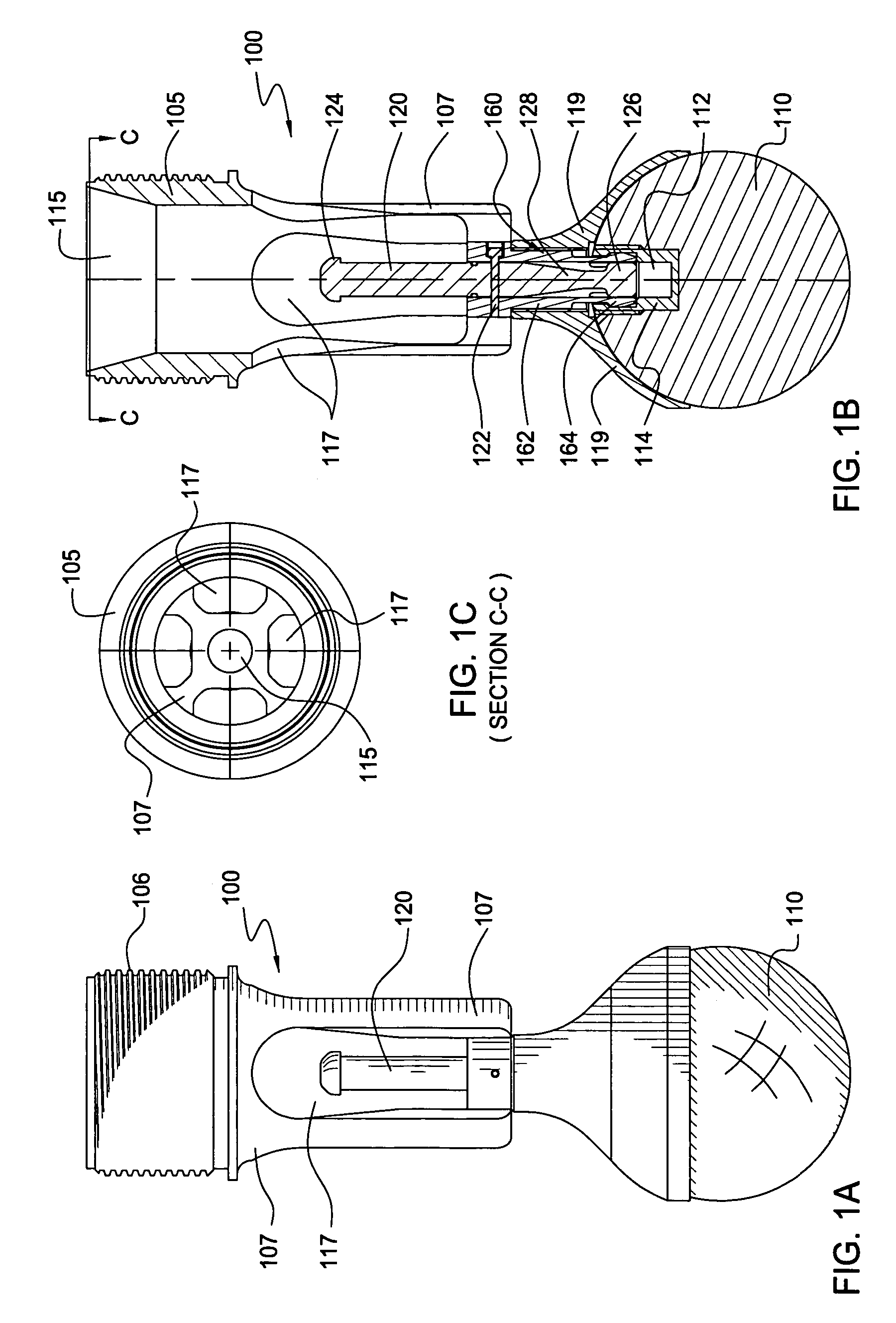
[0039]FIG. 1A presents a perspective view of a ball-releasing apparatus 100, in one embodiment, of the present invention. The ball-releasing apparatus 100 provides a novel mechanism for selectively releasing a larger ball 110 into a wellbore from a point below a wellbore restriction. The larger ball 110 is shown releasably attached to the ball-releasing apparatus 100. FIG. 1B is a cross-sectional view of the ball-releasing apparatus 100 of FIG. 1A. FIG. 1C is a top, cross-sectional view taken across line C—C of FIG. 1B.

[0040]The ball-releasing apparatus 100 first comprises a tubular body 105. The body 105 is configured and dimensioned to be received at the lower end of a mandrel within a wellbore tool (not shown in FIGS. 1A–1C). Preferably, the upper end of the body 105 has external threads 106 that allow the ball-releasing mechanism 100 to be quickly and simply screwed into the lower end of the mandrel.

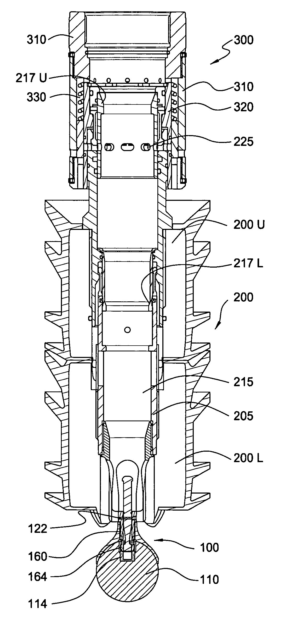
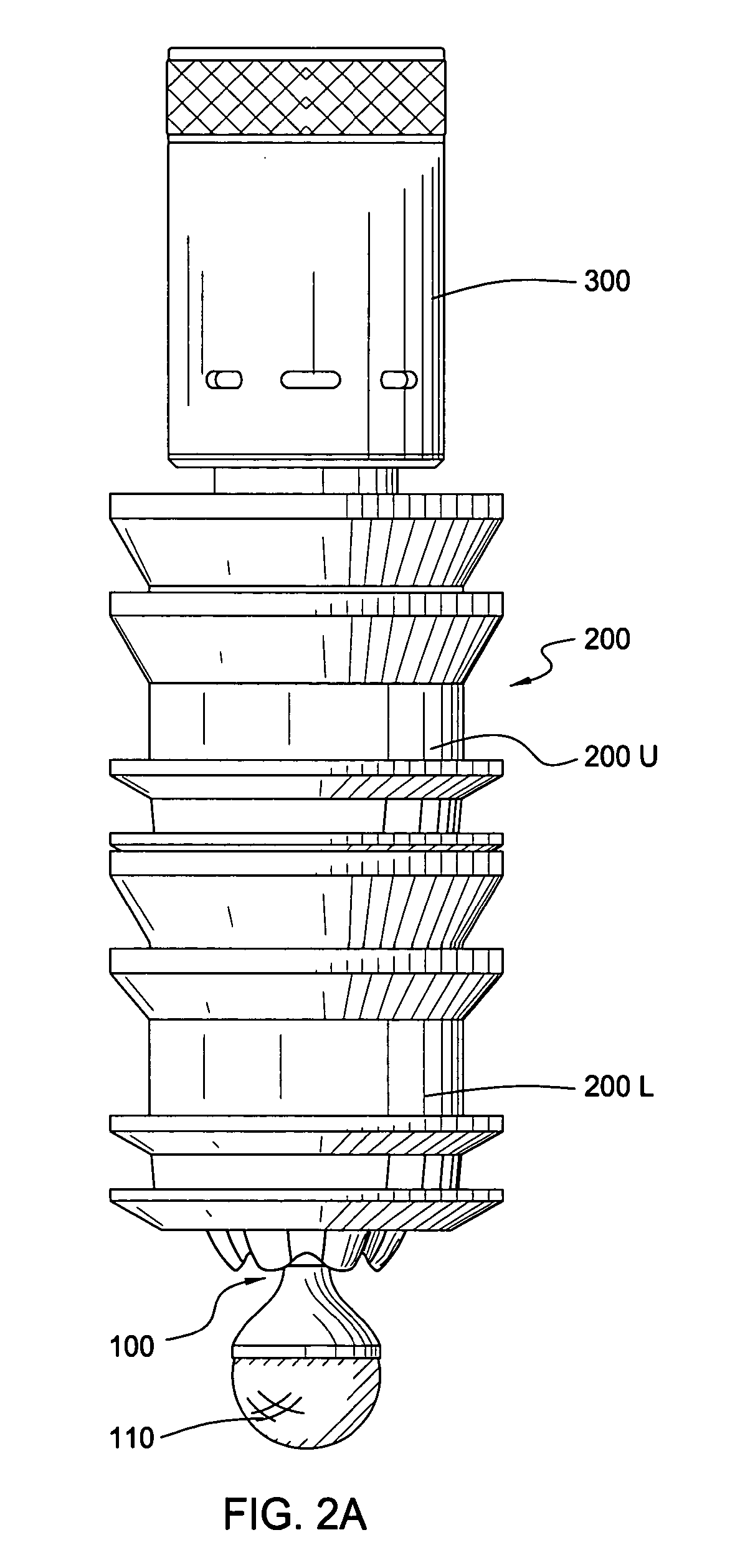
[0041]An example of a wellbore tool 200 for receiving the ball-releasing apparat...


PUM


Abstract

The present invention relates to an apparatus for dropping a ball into a wellbore. The apparatus is particularly useful for dropping a ball that has a diameter that is larger than the diameter of a bore within a wellbore tool above the apparatus. The ball-releasing apparatus first comprises a tubular body. The tubular body has a bore therethrough that is in fluid communication with the bore of the wellbore tool. A piston is placed within the tubular body. The piston has a top end disposed within the tubular body, and a bottom end disposed below the bore of the wellbore tool. The ball-releasing apparatus further comprises a connector for releasably connecting the piston to the ball. In one arrangement, the ball-releasing apparatus is connected to the bottom of a wiper plug for dropping a ball during a wellbore cementing operation. In one aspect, the ball is dropped by dropping a second ball having a diameter that will pass through the wellbore restriction, and then injecting fluid under pressure against the second smaller ball in order to actuate the releasable connection.

Description

CROSS-REFERENCE TO RELATED APPLICATIONS[0001]This application is a divisional of U.S. patent application Ser. No. 10,208,724, filed Jul. 30, 2002 now U.S. Pat. No. 6,802,372. Each of the aforementioned related patent applications is herein incorporated by reference.BACKGROUND OF THE INVENTION[0002]1. Field of the Invention[0003]The present invention generally relates to an apparatus for dropping balls into a wellbore. More particularly, the invention relates to a sub, such as a cement plug, capable of selectively releasing balls and other objects into a wellbore, such as during cementing operations. The invention further relates to a pressure equalizer and cross-over device as might be employed during a fluid circulation operation.[0004]2. Description of the Related Art[0005]In the drilling of oil and gas wells, a wellbore is formed using a drill bit that is urged downwardly at a lower end of a drill string. After drilling a predetermined depth, the drill string and bit are removed ...

Claims


Application Information

Patent Timeline
Patent Type & Authority Patents(United States)
IPC IPC(8): E21B33/12E21B33/16E21B34/14
CPCE21B33/16E21B34/14E21B34/142
Inventor BUDDE, MARCEL
Owner WEATHERFORD NETHERLANDS BV
Why Eureka
Try Eureka