Electrical connector with guidance face

a technology of electrical connectors and guides, applied in the direction of coupling device connections, coupling protective earth/shielding arrangements, electric discharge lamps, etc., can solve the problems of difficult signal transmission between electrical boards and contact damage, and achieve excellent signal transmission and avoid contact damage

Inactive Publication Date: 2006-12-05
HON HAI PRECISION IND CO LTD
View PDF62 Cites 18 Cited by
  • Summary
  • Abstract
  • Description
  • Claims
  • Application Information

AI Technical Summary

Benefits of technology

[0007]To achieve the above object, an electrical connector in accordance with the present invention for mating with a mating connector includes an insulating housing, a number of electrical contacts received in the housing. The housing has a mating face, a mounting face, two opposite side walls for connecting the mating face and the mounting face, a receiving space depressed in the mating face is formed between the side walls. A guidance face is formed on the inner face of the sidewalls extending from the mating face to the deep-lever of the receiving space, which includes an arc face and a slant face tangent to the arc face. Each contact has a contacting face exposed to the receiving space. This structure can make the contacts of the mating connector move without any friction so that damage of the contacts is avoided when the mating connector is inserted in, hence an excellent signal transmission between the electrical connectors is ensured.

Problems solved by technology

In this condition, if the female connector is short of a good guidance for the contacts of the male connector, the contacts of the male connector will move along a wrong direction and impact with the contacts of the female connector, and this commonly leads to the damage of the contacts and a difficult transmission of signal between the electrical boards.

Method used


Image

  • Electrical connector with guidance face
  • Electrical connector with guidance face
  • Electrical connector with guidance face

Examples


Embodiment Construction

[0013]Reference will now be made in detail to the preferred embodiment of the present invention.

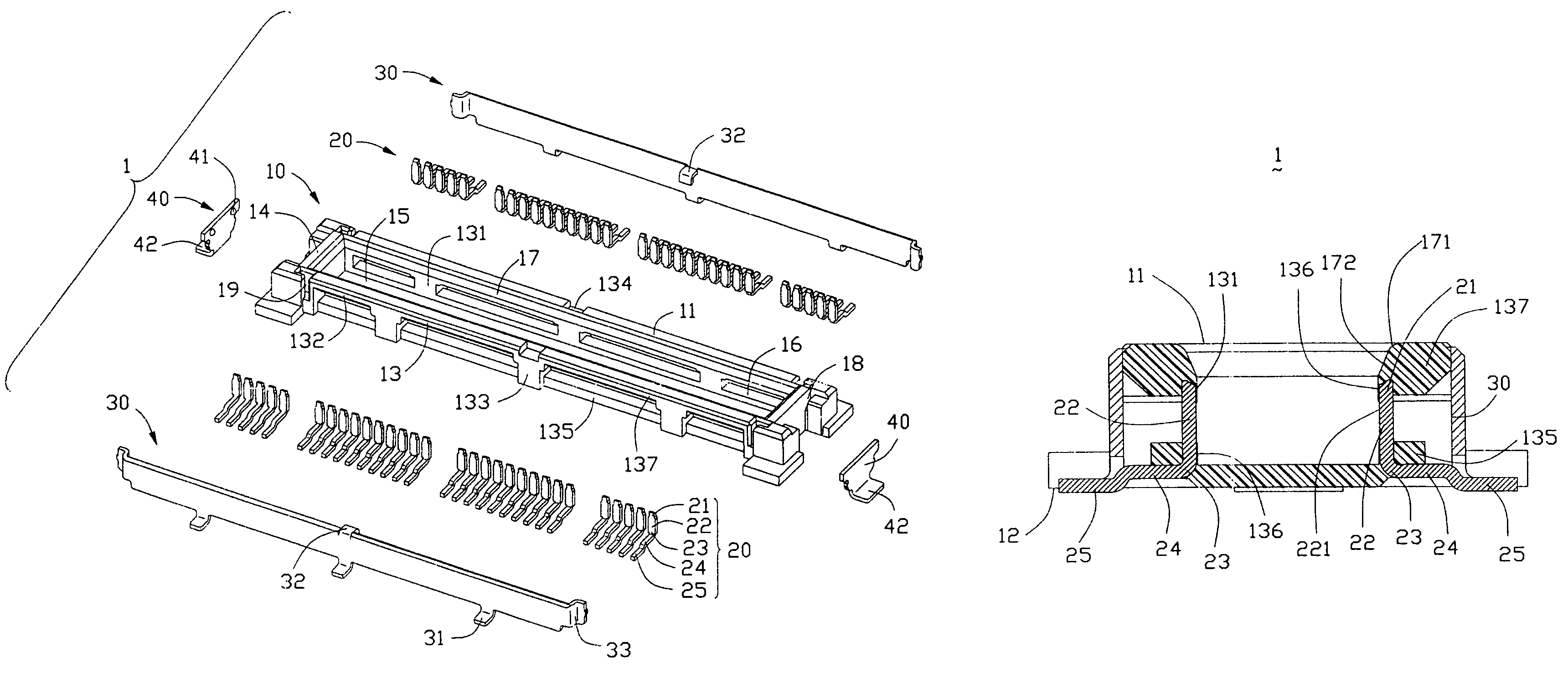
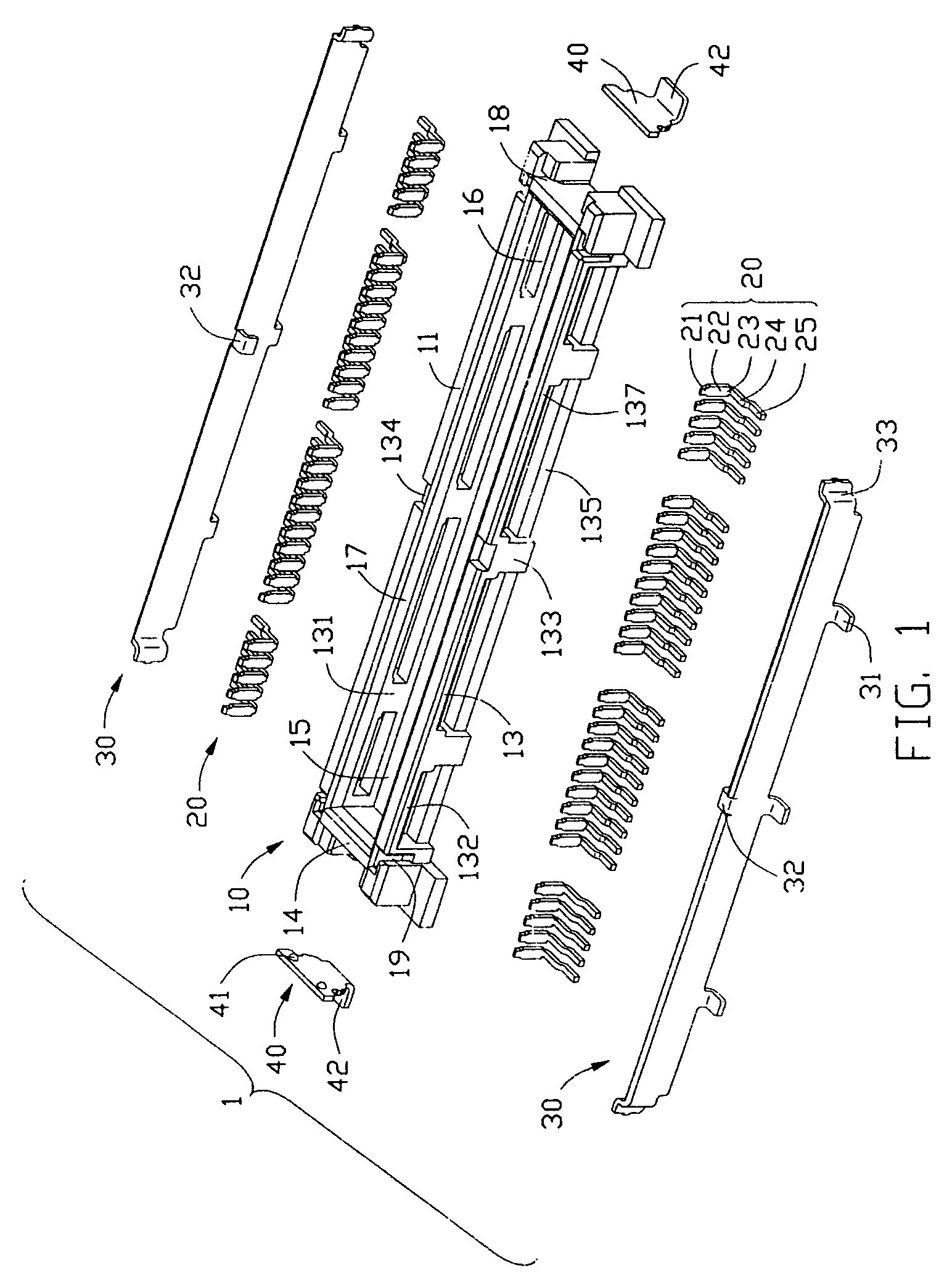
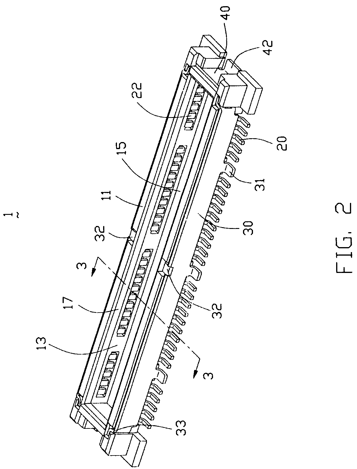
[0014]Please referring to FIGS. 1–2, an electrical connector 1 is mountable to an printed circuit board (PCB) (not shown) and engagable with a mating connector (not shown). The electrical connector 1 comprises an elongated insulative housing 10, a plurality of electrical conductive contacts 20 received in the housing 10, two shieldings 30 mounted on two sides of the housing 10, and a pair of “L” shaped metal pieces 40 received in two ends of the housing 10.

[0015]Referring to FIGS. 1–3, the housing 10 made of plastic material has a mating face 11 and a mounting face 12 opposite to the mating face 11, and the housing 10 comprises two opposing elongated sidewalls 13 extending from the mating face 11 to the mounting face 12 and a pair of opposing end walls 14 formed between the mounting face 12 and the mating face 11 and connecting with the sidewalls 13. An elongate receiving space 15 is depr...


PUM


Abstract

An electrical connector (1) for mating with a mating connector includes an insulating housing (10), a number of electrical contacts (20) received in the housing (10). The housing (10) has a mating face (11), a mounting face (12), two opposite side walls (13) for connecting the mating face and the mounting face, a receiving space (15) depressed in the mating face is formed between the side walls. A guidance face (17) is formed on the inner face (131) of the sidewalls extending from the mating face to the deep-lever of the receiving space, which includes an arc face (171) and a slant face (172) tangent to the arc face. Each contact has a contact face (221) exposed to the receiving space.

Description

BACKGROUND OF THE INVENTION[0001]1. Field of the Invention[0002]The present invention generally relates to an electrical connector and more particularly, to the electrical connector having a plurality of contacts insert molded within and having a guidance face to decrease the possibility of deformation of the contacts under connection force.[0003]2. Description of Related Art[0004]Electrical connectors well known in the art are used in a variety of applications and develop in a tendency of minitype and integration. Such connectors are provided as a connection between two opposite circuit boards. This type of connectors is referred to in the art as board to board connectors and typically include opposing interengaging male and female connector assembly, each of that has a housing having a plurality of contacts therein. The female connector may typically includes a receiving space for receiving the male connector in a connective relationship. However, a variety of oblique insertion ma...

Claims


Application Information

Patent Timeline
Patent Type & Authority Patents(United States)
IPC IPC(8): H01R24/00H01R12/16H01R13/631
CPCH01R12/716H01R13/631H01R23/6873H01R12/707H01R13/658
Inventor PAN, WEIHUAZHANG, MING
Owner HON HAI PRECISION IND CO LTD
Why Eureka
Try Eureka