Traction method and device

Active Publication Date: 2006-12-05
GOLDBERG ELLIOTT
View PDF27 Cites 9 Cited by
  • Summary
  • Abstract
  • Description
  • Claims
  • Application Information

AI Technical Summary

Benefits of technology

[0014]Another object of the present invention is to provide traction through a compact spring arrangement configured to optimally direct forces along the spine of the patient.

Problems solved by technology

This can result in a variety of symptoms including neck, shoulder, back and extremity pain, tension, and stress symptom of the neck and the trunk.
Specifically, although some of the attachments to the straps allow for significant application of large forces, there does not appear to be a way to adequately apply measured amounts of forces to the lower back in traction.
Specifically, assembly and disassembly are relatively tedious.
The water bag is t

Method used


Image

  • Traction method and device
  • Traction method and device
  • Traction method and device

Examples


Embodiment Construction

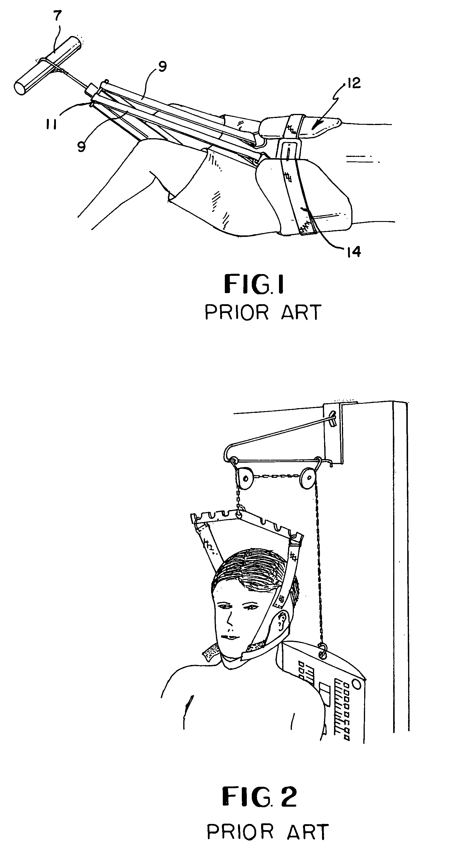
[0026]Referring to FIG. 1, a typical prior art lumbar traction device and its use is illustrated. The device includes a pelvic harness 12 which is available from several vendors. The pelvic harness 12 is placed about the waist of the person and the belt strap(s) 14 connected as illustrated in FIG. 1. Traction straps 9 typically connect the pelvic harness 12 to a force applicator, illustrated as a fixed support 7 in FIG. 1. The patient either pushes away from the force applicator or the force applicator exerts a force on the patient so that traction is applied to the lower portion of the patient's spine.

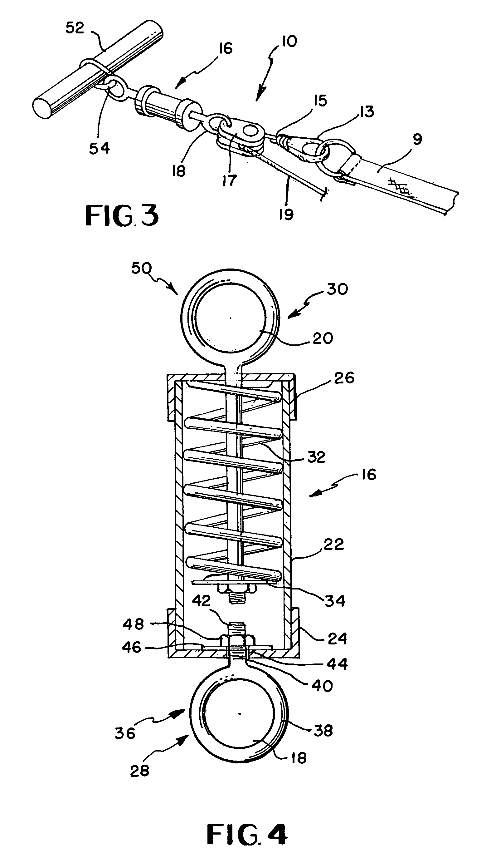
[0027]Instead of connecting the pelvic harness 12 to a spreader bar 11 as is illustrated in FIG. 1, the design disclosed herein connects the traction straps 9 of the pelvic harness 12 to a clip 13 as illustrated in FIG. 3. However a spreader bar could also be utilized, if so desired. The clip 13 may be a carabiner as is often utilized in climbing, or other appropriate connecting devic...


PUM


Abstract

A traction device utilizes a harness connected to the body of a patient, such as the head or hips. The harness is connected by a clip to a tether which passes through a ratchet pulley connected to a first end of a spring chamber. A second end of the spring chamber is connected to a support. As tension is applied to the tether, the ratchet pulley incrementally applies traction to the patient as a first spring housed within the spring chamber deflects with the application of force.

Description

[0001]This invention claims the benefit of U.S. Provisional Patent Application Nos. 60 / 326,873 filed Oct. 2, 2001 and 60 / 307,266 filed Jul. 23, 2001.BACKGROUND OF THE INVENTION[0002]1. Field of the Invention[0003]This invention relates to a traction method and device, and more particular to a method and device for applying traction to a portion of the spine, either along an upper portion or along a lower portion for cervical or lumbar traction.[0004]2. Prior Art[0005]The spine is made up of vertebrae spaced apart by members commonly known as discs. If these discs become compressed to the point of herniation, they exert pressure on nerves passing between the vertebrae. This can result in a variety of symptoms including neck, shoulder, back and extremity pain, tension, and stress symptom of the neck and the trunk. It is known that traction applied to the spine will, in many cases, stretch out the spine and allow the discs to become de-compressed, somewhat reversing the herniation resu...

Claims


Application Information

Patent Timeline
IPC IPC(8): A61F5/00A61F5/04A61F5/055
CPCA61F5/04A61F5/055
Inventor GILLIAM, LARRY A.
Owner GOLDBERG ELLIOTT
Why Eureka
Try Eureka