Apparatus for connecting a longitudinal member to a bone portion

Inactive Publication Date: 2006-12-05
ZIMMER BIOMET SPINE INC
View PDF56 Cites 344 Cited by
  • Summary
  • Abstract
  • Description
  • Claims
  • Application Information

AI Technical Summary

Benefits of technology

[0009]A spacer received in the second passage of the housing is engageable with the fastener and the longitudinal member. A positioning member applies a force to prevent relative movement between the fastener and the housing when the longitudinal member is disengaged from the spacer and the spacer engages the fastener. The fastener and the housing are manually movable relative to each other against the force when the longitudinal member is disengaged from the spacer and the positioning member applies the force. Accordingly, an advantage of the present invention is that the housing and the fastener can be positioned relative to each other and the member will hold the fastener and the housing in the relative positions before the longitudinal member is connected to the housing. In the absence of a positioning member, the movement of the housing relative to the fixation element is relatively unrestricted, and can prove cumbersome, particularly in minimally invasive procedures performed via a cannula. A clamping mechanism clamps the longitudinal member, the spacer, and the housing to the fastener to prevent movement of the fastener, the housing, and the longitudinal member relative to each other.
[0010]In a first embodiment of the present invention the positioning member is a compression member, for example a spring member applying the force to partially or completely restrict relative movement between the fastener and the housing when the longitudinal member is disengaged from the spacer and the spacer engages the fastener. The spring member maintains the spacer in frictional engagement with the fastener and the fastener in frictional engagement with the housing.
[0011]In another embodiment of the present invention, the positioning member is a pin member applying a force to partially or completely restrict relative movement between the fastener and the housing when the longitudinal member is disengaged from the spacer and the spacer engages the fastener. The pin member is fixedly connected to the housing and extends from the housing into engagement with the spacer to retain the spacer and the fastener in the housing. The pin member maintains the spacer in frictional engagement with the fastener and the fastener in frictional engagement with the housing.
[0012]In another embodiment of the present invention, a retaining ring holds the spring member and the spacer in the housing. The retaining ring is press-fit into the housing so that the amount of force applied by the spring member may be adjusted.

Problems solved by technology

In the absence of a positioning member, the movement of the housing relative to the fixation element is relatively unrestricted, and can prove cumbersome, particularly in minimally invasive procedures performed via a cannula.

Method used


Image

  • Apparatus for connecting a longitudinal member to a bone portion
  • Apparatus for connecting a longitudinal member to a bone portion
  • Apparatus for connecting a longitudinal member to a bone portion

Examples


Embodiment Construction

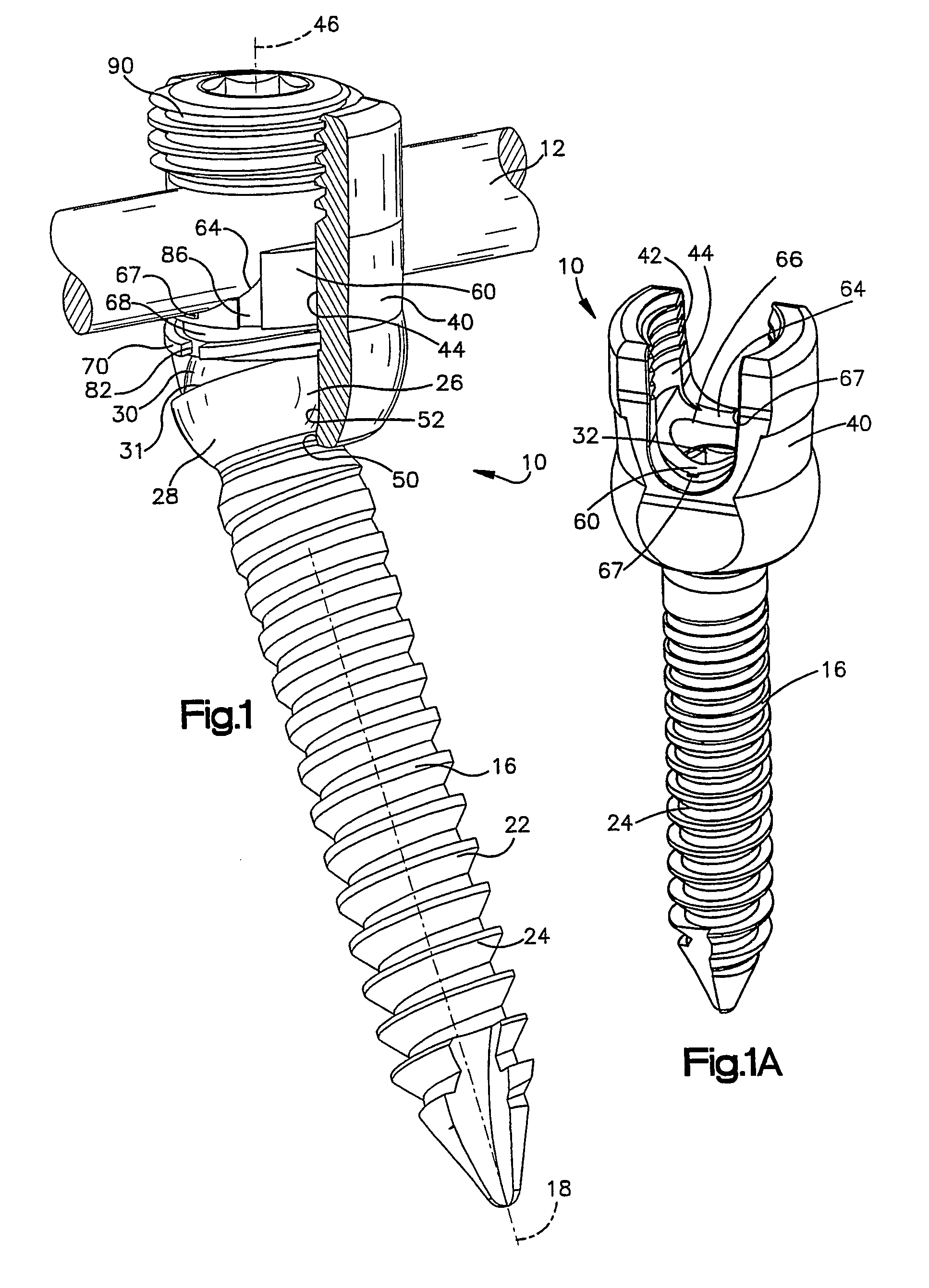
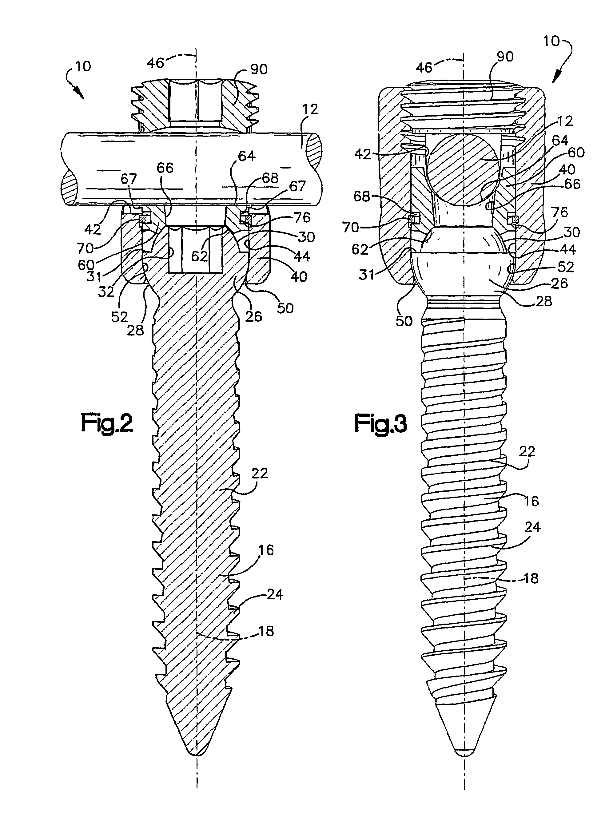
[0039]The present invention is directed to an apparatus for retaining bone portions, such as vertebrae of a spinal column, in a desired spatial relationship. FIGS. 1–4 illustrate an apparatus 10 constructed according to a first embodiment of the present invention. The apparatus 10 includes a surgically implantable longitudinal member or rod 12 for maintaining bone portions, such as vertebrae of a spinal column, in a desired spatial relationship. The member 12 is connected with vertebrae of the spinal column by fasteners 16.

[0040]The rod 12 is made of a suitable biocompatible material and has a length which is at least sufficient to enable the rod to span at least two vertebrae. Of course, the length of the rod 12 in any particular installation will depend upon the condition to be corrected and the number of vertebrae to be held in a desired spatial relationship relative to each other by the rod.

[0041]The rod 12 (FIGS. 1–3) is connected to a respective vertebra by the fastener 16 mad...


PUM


Abstract

An apparatus (10) includes a fastener (16) engageable with a bone portion to connect a longitudinal member (12) to the bone portion. A housing (40) has a first passage (42) configured to receive the longitudinal member and a second passage (44) extending transverse to the first passage. The fastener extends through an opening (50) in the housing into the second passage. A longitudinal axis (18) of the fastener is positionable in any one of a plurality of angular positions relative to a longitudinal axis (46) of the second passage. A spacer (60) received in the second passage of the housing is engageable with the fastener and the longitudinal member. A positioning member (70) applies a force to prevent relative movement between the fastener and the housing and permit manual movement of the fastener relative to the housing against the force when the longitudinal member is disengaged from the spacer. A clamping mechanism (90) clamps the longitudinal member, the spacer, and the housing to the fastener to prevent movement of the fastener relative to the housing.

Description

RELATED APPLICATIONS[0001]This application is a continuation-in-part of application serial numbers 10 / 075,668, filed Feb. 13, 2002 and 10 / 087,489, filed Mar. 1, 2002.TECHNICAL FIELD[0002]The present invention relates to an apparatus which is used to retain bone portions, such as vertebrae of a spinal column, in a desired spatial relationship.BACKGROUND OF THE INVENTION[0003]The human spine is configured to maintain an upright posture and, as such, must be capable of supporting substantial weight. Injuries or deformities of the spine may compromise this function. Orthopedic surgery to treat such conditions will often insert implants, for example a metal rod connected to sequential vertebrae via bone screws, to fix the position of the vertebrae and thereby stabilize the spine and augment support.[0004]The first generation of vertebral screws could be connected to a rod in a single orientation (“monoaxial screws”). Variations in anatomy and difficulties in screw placement would frequen...

Claims


Application Information

Patent Timeline
Patent Type & Authority Patents(United States)
IPC IPC(8): A61B17/56A61F2/30A61B17/58A61B17/70
CPCA61B17/7032A61B17/7037
Inventor SHLUZAS, ALAN E.
Owner ZIMMER BIOMET SPINE INC
Why Eureka
Try Eureka