Foldable projection lenses

a projection lens and lens body technology, applied in the field of folding projection lenses, can solve the problems of lateral color, i.e., the variation of magnification with color, and the inability to perform accommodation, so as to avoid the problem of apparent distortion, the effect of high distortion correction level and sensitive to curvatur

Inactive Publication Date: 2006-12-05
3M INNOVATIVE PROPERTIES CO
View PDF17 Cites 69 Cited by
  • Summary
  • Abstract
  • Description
  • Claims
  • Application Information

AI Technical Summary

Problems solved by technology

Lateral color, i.e., the variation of magnification with color, is particularly troublesome since it manifests itself as a decrease in contrast, especially at the edges of the field.
With a pixelized panel, however, such an accommodation cannot be performed because the image is digitized and thus a smooth adjustment in size across the full field of view is not possible.
The use of a pixelized panel to display data leads to stringent requirements regarding the correction of distortion.
Because the operation of DMDs and reflective LCDs depend upon their ability to reflect light efficiently, projection systems employing panels of these types are particularly susceptible to ghost problems.
Although successful in reducing aberrations, this approach lessens the amount of light which reaches the corners and thus produces an image whose brightness is lower in the corners than at the center.
The use of special glasses in a projection lens can rapidly increase the lens' cost, especially if such glasses are used in large lens elements.
This makes the lens asymmetric about the aperture stop which makes the correction of lateral color more difficult.
The requirement for a large field of view makes it even more difficult to correct the lateral color of the lens.
This is especially so when combined with the requirement for a relatively long effective back focal length which itself makes it more difficult to correct lateral color.
Also, as mentioned above, the requirement for telecentricity is a third factor which makes the correction of lateral color challenging.
A construction of this type makes it more difficult to correct the aberrations of the system, especially if the lens is to include only a relatively small number of lens elements as is desired to reduce the cost, weight, and complexity of the projection lens.
Achieving a relatively long back focal length, a wide field of view in the direction of the lens' long conjugate, telecentricity, and a folded configuration, while still maintaining high levels of aberration correction with minimal vignetting and low levels of ghost generation, is particularly challenging since these various requirements tend to work against one another.
To do so while reducing the overall cost of the projection lens is even more demanding.

Method used


Image

  • Foldable projection lenses
  • Foldable projection lenses
  • Foldable projection lenses

Examples


examples

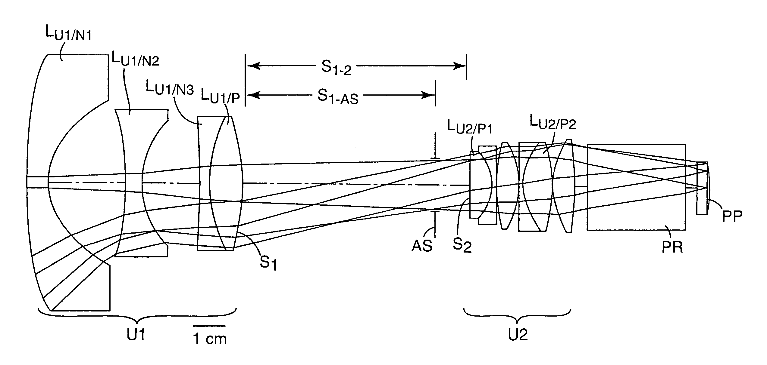
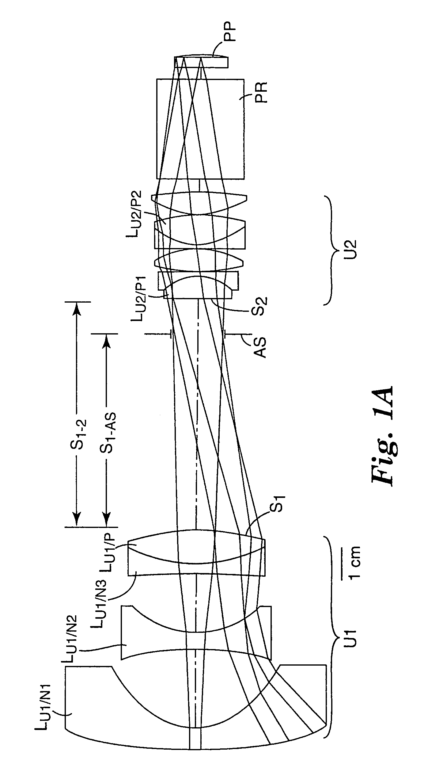
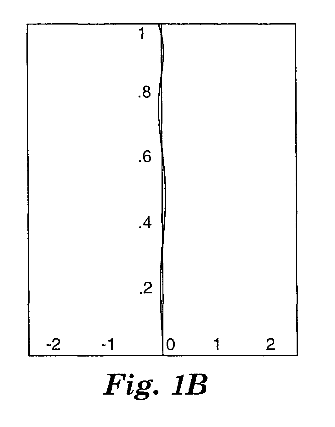
[0128]FIGS. 1–5 and Tables 1–5 illustrate representative projection lenses constructed in accordance with the invention.

[0129]OHARA designations are used for the various glasses employed in the lens systems. Equivalent glasses made by other manufacturers (e.g., HOYA or SCHOTT) can be used in the practice of the invention. Industry acceptable materials are used for the plastic elements.

[0130]The aspheric coefficients set forth in the tables are for use in the following equation:

[0131]z=⁢cy21+[1-(1+k)⁢⁢c2⁢y2]1 / 2+⁢Dy4+Ey6+Fy8+Gy10+Hy12+Iy14

where z is the surface sag at a distance y from the optical axis of the system, c is the curvature of the lens at the optical axis, and k is a conic constant, which is zero except where indicated in the prescriptions of Tables 1–5.

[0132]The designation “a” associated with various surfaces in the tables represents an aspherical surface, i.e., a surface for which at least one of D, E, F, G, H, or I in the above equation is not zero; and the designation...


PUM


Abstract

Projection lenses for use with pixelized panels (PP) are provided. The projection lenses have a first unit (U1) separated from a positive second unit (U2) by a distance sufficient to accept a reflective surface (RS) for folding the lens' optical axis. The lenses are telecentric on the short conjugate side, have a large field of view in the direction of the long conjugate, and have low aberration levels. By using negative lens elements (LU1 / N1 and LU1 / N2) composed of plastic materials having large positive Q-values at the long conjugate side of the first lens unit (U1), the lenses can achieve low levels of lateral color, including low levels of secondary lateral color, with reduced cost compared to lenses which employ anomalous dispersion glasses in the first lens unit.

Description

CROSS REFERENCE TO RELATED APPLICATION[0001]This application claims the benefit under 35 USC § 119(e) of U.S. Provisional Application No. 60 / 598,611, filed on Aug. 4, 2004, and entitled FOLDABLE PROJECTION LENSES, the contents of which are incorporated herein in their entirety.[0002]This invention relates to projection lenses and, in particular, to foldable, telecentric projection lenses for use in forming an image of an object composed of pixels, such as, a DMD, a reflective LCD, a transmissive LCD, or the like. The lenses are particularly well-suited for use with DMD panels.BACKGROUND OF THE INVENTION[0003]A. Definitions[0004]As used in this specification and in the claims, the following terms shall have the following meanings:[0005](1) Telecentric[0006]Telecentric lenses are lenses which have at least one pupil at infinity. In terms of principal rays, having a pupil at infinity means that the principal rays are parallel to the optical axis (a) in object space, if the entrance pup...

Claims


Application Information

Patent Timeline
Patent Type & Authority Patents(United States)
IPC IPC(8): G02B3/00
CPCG02B9/10G02B13/16G02B13/18G02B13/22
Inventor KREITZER, MELVYN H.MOSKOVICH, JACOB
Owner 3M INNOVATIVE PROPERTIES CO
Why Eureka
Try Eureka