Semiconductor storage device
a storage device and semiconductor technology, applied in the field of semiconductor storage devices, can solve the problems of reducing the busy rate of refresh compared with the conventional dram, affecting and affecting the fabrication of semiconductor devices, so as to achieve the effect of not lowering the performance of read/write operations
- Summary
- Abstract
- Description
- Claims
- Application Information
AI Technical Summary
Benefits of technology
Problems solved by technology
Method used
Image
Examples
first embodiment
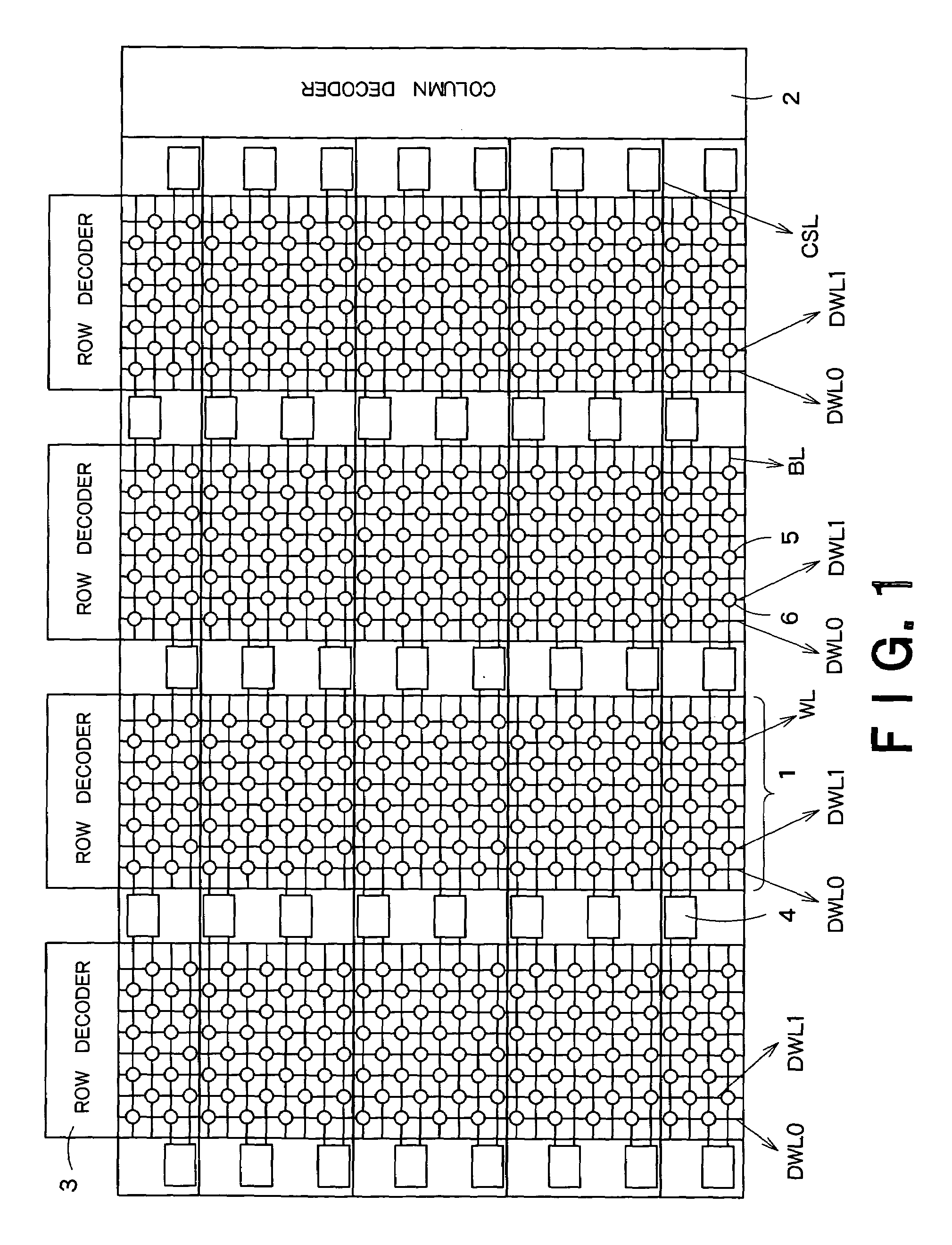
[0016]FIG. 1 is an array configuration of a semiconductor storage device according to a first embodiment of the present invention. The semiconductor apparatus shown in FIG. 1 includes a plurality of cell arrays 1, a column decoder 2 provided corresponding to the cell arrays, row decoders 3 provided for respective cell arrays 1, and double-end type sense amplifiers 4 provided between cell arrays 1 and on both sides of cell arrays 1.
[0017]Each cell array 1 includes a plurality of bit lines BL arranged in the column direction, a plurality of word lines WL arranged in the row direction, two dummy word lines DWL0 and DWL1, FBCs 5 each disposed near at the intersection of a bit line BL and a word line WL, and dummy cells 6 disposed near at the intersection of a bit line and a dummy word line.
[0018]The dummy cells 6 are the same as the FBCs 5 in size, shape and electric characteristics. Data “0” and data “1” are alternately written into the dummy cells 6 for respective columns.
[0019]In eac...
second embodiment
[0042]In a second embodiment, sense operation is conducted without using the dummy cells 6.
[0043]FIG. 4 is an array configuration diagram of an FBC 5 memory according to the second embodiment of the present invention. In the FBC 5 memory shown in FIG. 4, only FBCs 5 are provided, and dummy cells 6 do not exist. A reference voltage VREF is input to all sense amplifiers 4 from the outside of the array.
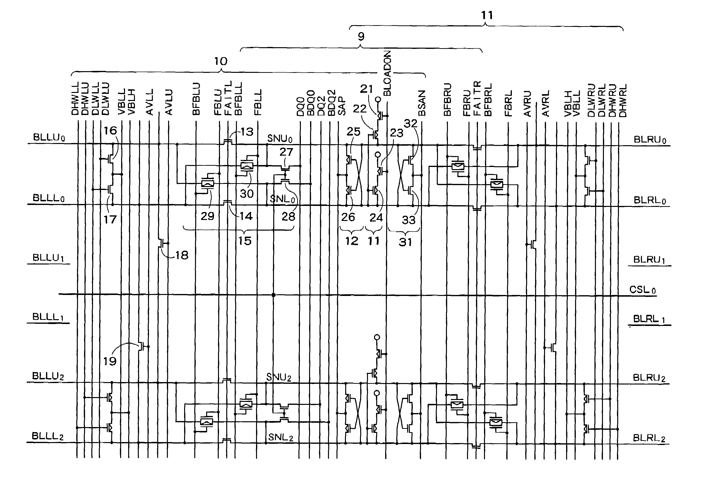
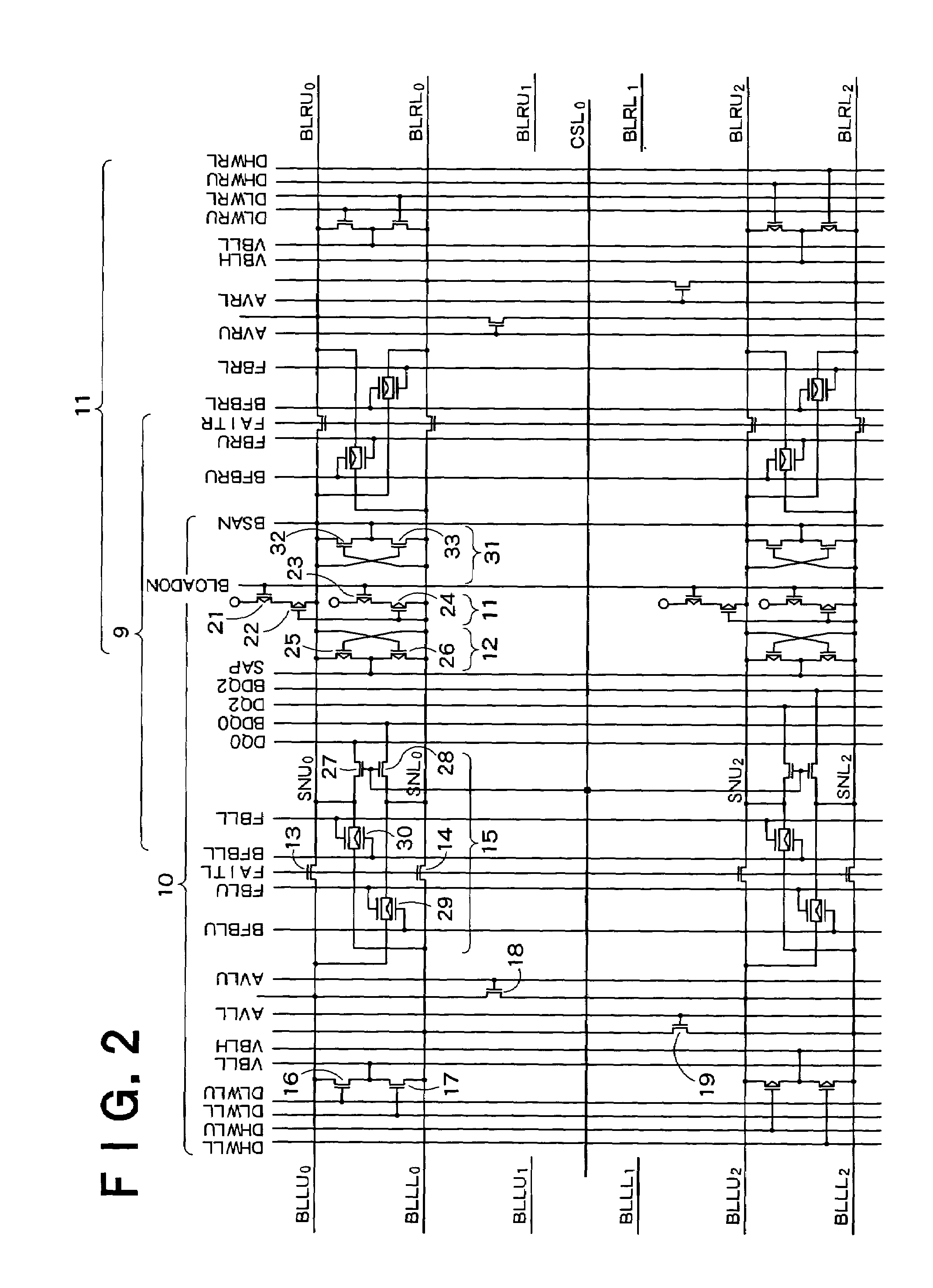
[0044]FIG. 5 is a circuit diagram showing an example of an internal configuration of the sense amplifier 4 in the second embodiment. In FIG. 5, components common to those shown in FIG. 2 are denoted by like characters, and hereafter mainly different points will be described.
[0045]The sense amplifier 4 shown in FIG. 5 has transistors 41 and 42 for setting each bit line to a reference potential VREF. Instead, the transistors for short-circuiting bit lines shown in FIG. 2 do not exist.
[0046]The reference potential VREF is an intermediate potential between VBLL and VBLH. It is necessary to g...
PUM
 Abstract
Description
Claims
Application Information
 - R&D
- Intellectual Property
- Life Sciences
- Materials
- Tech Scout
- Unparalleled Data Quality
- Higher Quality Content
- 60% Fewer Hallucinations
Browse by: Latest US Patents, China's latest patents, Technical Efficacy Thesaurus, Application Domain, Technology Topic, Popular Technical Reports.
© 2025 PatSnap. All rights reserved.Legal|Privacy policy|Modern Slavery Act Transparency Statement|Sitemap|About US| Contact US: help@patsnap.com


