Continuously variable mechanical transmission

a mechanical transmission and continuously variable technology, applied in the direction of gearing, gearing elements, hoisting equipment, etc., can solve the problems of large number of gear changes required for efficient operation, transmissions that do not have high efficiency or smooth operation, and cannot automatically change the speed ratio without manually changing gears, etc., to achieve convenient and economic production, simple in principle, and convenient in operation

Inactive Publication Date: 2006-12-12
KAPLUN GREGORY
View PDF11 Cites 8 Cited by
  • Summary
  • Abstract
  • Description
  • Claims
  • Application Information

AI Technical Summary

Benefits of technology

[0007]The object of the present invention is to have a continuously variable mechanical transmission system. The step less ratio change takes advantage of the fact that a hemisphere rotating around its polar axis has larger length of circumference at its major diameter than close to its tip, because the radius of a hemisphere is a constant the transition from the major diameter to a minor produces step less length of circumference change without changing the point of engagement between the hemisphere wheel and a second wheel. The present invention can be adapted to any mechanical variable output device. The hemisphere wheel thus would be mounted on the bearing. The inside race of the bearing would have two opposing pivot points inside the wheels major diameter, allowing the wheel to swing around the mounting fork, the fork is attached to the wall of the transmission. A variation on the mounting scheme would be the wheel to have a cylindrical extension from its major diameter. The extension would be mounted inside the bearing. The outer race of the bearing would have two opposing pivot points extending back over the major diameter of the wheel. The pivot points would be mounted into the body of the transmission. The center of the hemisphere wheel would be connected to the driving shaft through a constant velocity device (single or double universal joint, flexible shaft or similar). Alternatively, a motor can be mounted on a stationary race of the bearing, with its shaft connected to the hemisphere wheel thus eliminating the need for a constant velocity device.
[0009]It is therefore an object of the present invention to provide an improved continuously variable mechanical transmission system which can be easily and economically produced, simple in principal, convenient in operation, sturdy in construction, highly efficient, long lasting and capable of operating under wide range of power and speed. It is another object of the invention to have a transmission with ratio of input to output that can be varied instead of fixed.
[0010]It is a further object of the present invention to have a continuously variable transmission system comprising: an input shaft is a flexible constant velocity device connected to a hemisphere wheel on the inside center of said hemisphere wheel and the hemisphere wheel having a bearing. A housing of the transmission having a mounting fork or other form of attachment to the hemisphere wheel at two pivot points on the stationary race of the bearing located on the inside circumference at the hemispheres major diameter or on the outside of it cylindrical extension. Further having a control lever with a joint attachment to the stationary race of the bearing that is perpendicular to the pivot points; and having an output shaft connected to a second wheel, and the second wheel's circumference engaged with the outside of said hemisphere wheel. Finally, the control lever having the ability to swing the hemisphere wheel around the pivot points to change the engaged diameter of the hemisphere wheel such that the difference in diameter from equator to pole creates a continuously variable transmission.

Problems solved by technology

It is a very efficient mechanism, but is incapable of automatically changing the speed ratio without manually changing gears.
As a result, a large number of gear changes are required for efficient operation.
These transmissions do not have high efficiency or smooth operation because they must have stepped speed ratio changes.
These transmissions generate high internal power losses.
Existing designs for continuously variable transmission such as “V” belt transmissions, Hydraulic transmissions and mechanical planetary gear and variable length lever transmissions lack efficiency, simplicity of operation, power transmission capability or operating speed range.

Method used


Image

  • Continuously variable mechanical transmission
  • Continuously variable mechanical transmission
  • Continuously variable mechanical transmission

Examples


Embodiment Construction

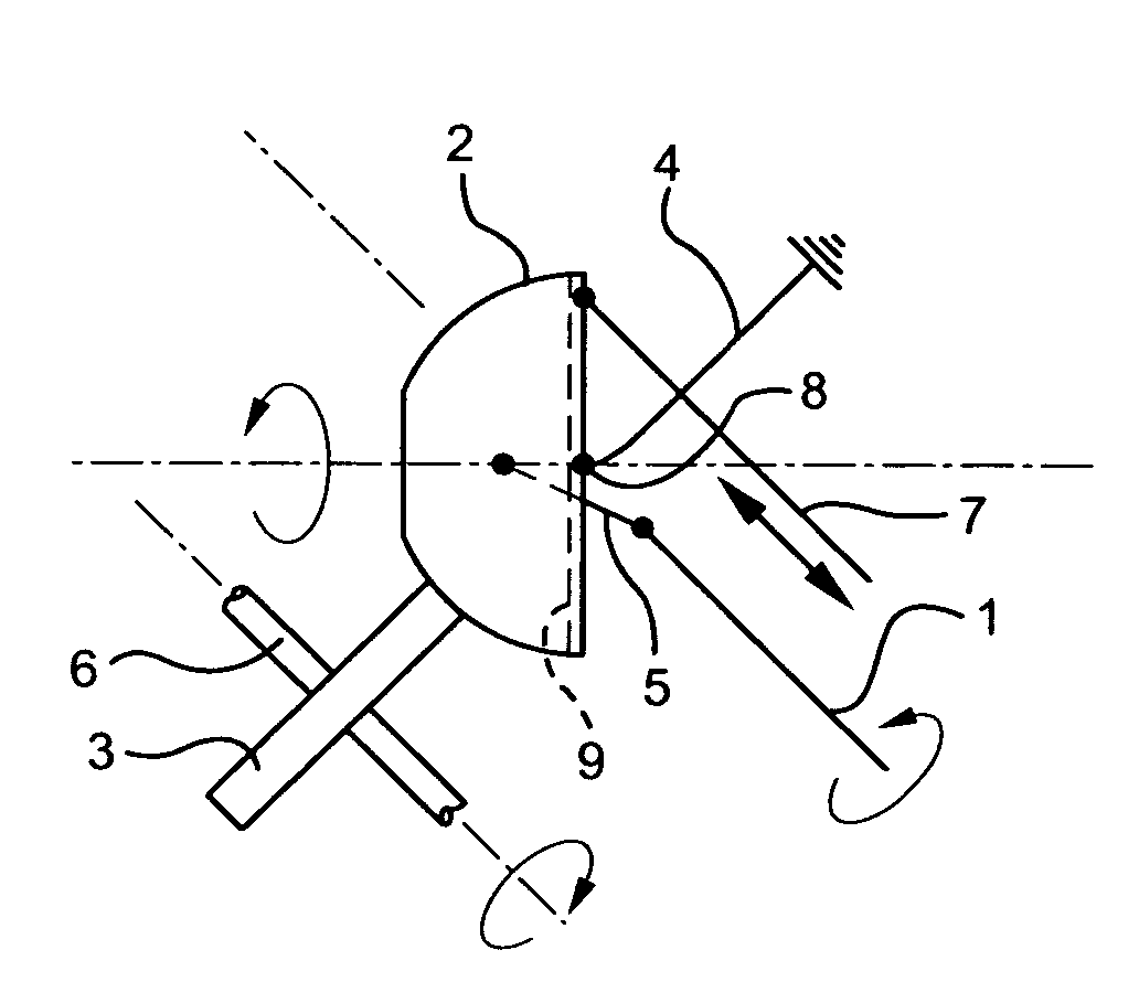
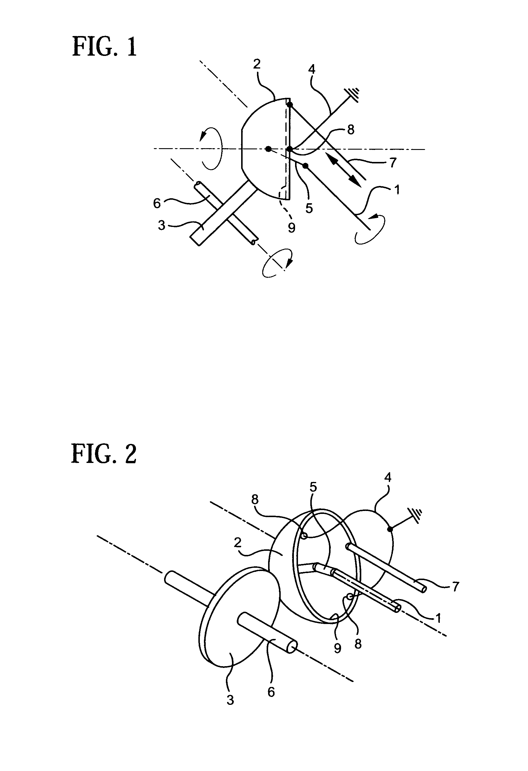
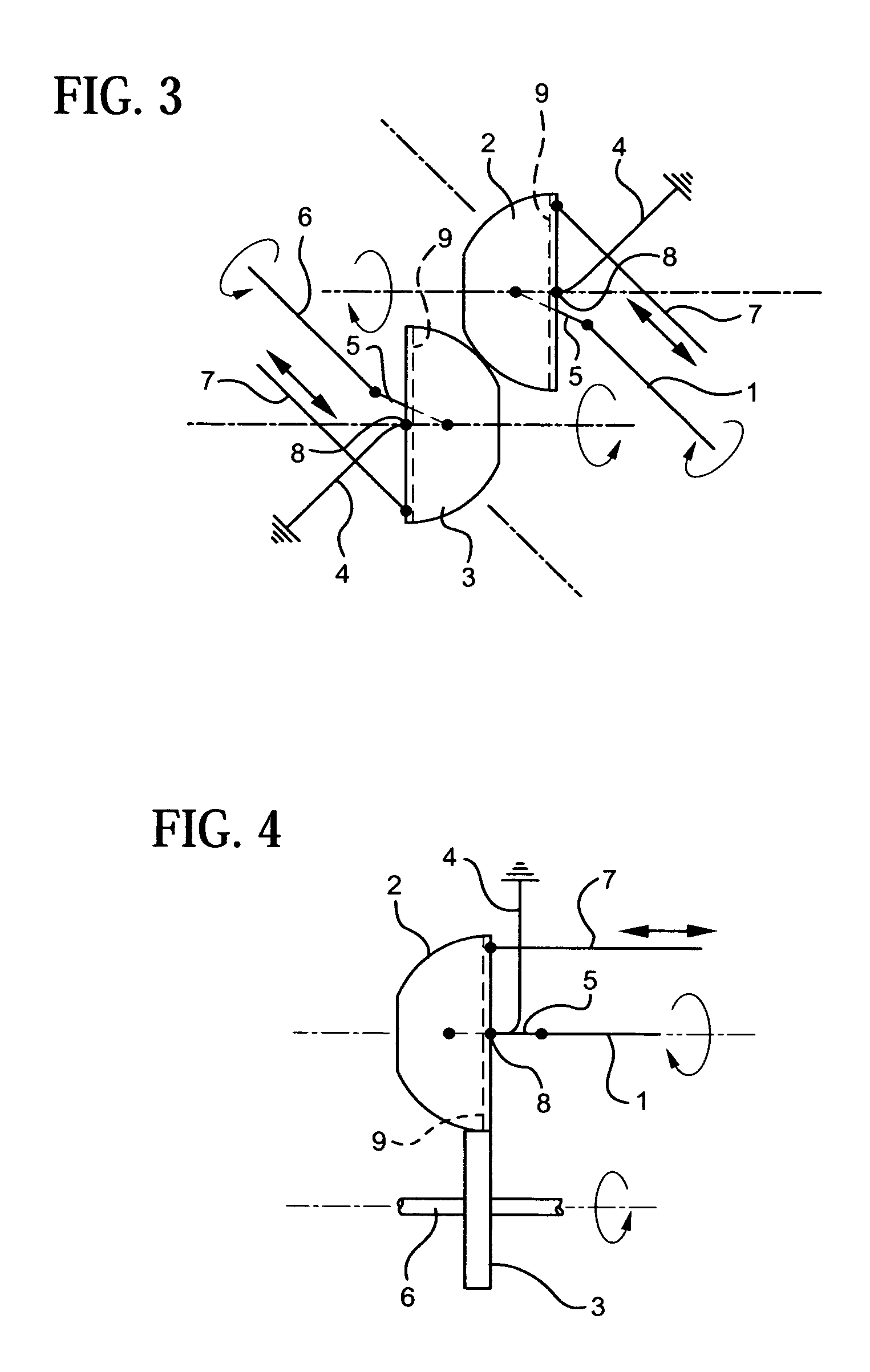
[0022]Referring to the FIG. 1, there is shown a first embodiment of the continuously variable mechanical transmission where input shaft 1 is connected to the hemisphere wheel 2 through a single or double universal joint 5 (FIG. 8 showing a single universal joint), flexible shaft or a similar constant velocity device. The hemisphere wheel is rotating on the bearing 9, the inner race of the bearing having two pivot points 8, attached to the mounting fork 4. The fork is fixed to the housing of the transmission (not shown). The fork 4 can be attached directly to the hemisphere wheel or, as well known in the art can have an intermediate member connecting the fork to the hemisphere wheel. The bearing 9 is located at the major diameter of the hemisphere wheel. However, as is well known in the art, the bearing can be in a number of places on the hemisphere wheel and is only a matter of design.

[0023]The control lever 7 determines the angle between the hemisphere wheel and the input shaft. Th...


PUM


Abstract

A continuously variable mechanical transmission comprised of two wheels, either friction or toothed, of which one or both are in the shape of hemispheres. A hemisphere wheel is mounted through a bearing on a mounting with two pivots attached to the outer race of the bearing, allowing the wheel to rotate around two perpendicular accesses. The center of the wheel is attached to the shaft through a single or double universal joint or a flexible shaft. The other wheel can be a regular narrow wheel fixed to the second shaft. By rotating the hemisphere wheel around the mounting pivots the diameter of the wheel engaged with the second wheel is increased or decreased allowing the transmission rate to vary.

Description

CROSS-REFERENCES TO RELATED APPLICATIONS[0001]This application is related to commonly-owned U.S. Pat. No. 6,467,374 entitled “A CONTINUOUSLY VARIABLE MECHANICAL TRANSMISSION” issued Oct. 22, 2002 with inventor Gregory Kaplun.BACKGROUND OF THE INVENTION[0002](1) Field of the Invention[0003]The invention relates to a mechanical transmission, and more particularly a mechanical transmission that is truly continuously variable.[0004](2) Description of the Prior Art[0005]The most common mechanical transmission in use today is the sliding gear transmission. It is a very efficient mechanism, but is incapable of automatically changing the speed ratio without manually changing gears. Most power sources can operate only over small speed range with good economy and power. As a result, a large number of gear changes are required for efficient operation.[0006]The present automatic and manual transmissions in use attempt to maximize operating economy and power through a constant maintenance of pow...

Claims


Application Information

Patent Timeline
Patent Type & Authority Patents(United States)
IPC IPC(8): F16H15/28F16H15/44
CPCF16H15/28F16H15/44
Inventor KAPLUN, GREGORY
Owner KAPLUN GREGORY
Why Eureka
Try Eureka