Clamp for flexible tubing

a flexible tubing and flexible technology, applied in the field of medical devices, can solve the problems of unintentional and undesirable delatching and unclamping from the tubing, failure and breakage, failure of the extension tube and blood loss from the catheter, etc., and achieves the effect of less length of tubing, and convenient removal

Inactive Publication Date: 2012-09-18
MEDICAL COMPONENTS INC
View PDF45 Cites 8 Cited by
  • Summary
  • Abstract
  • Description
  • Claims
  • Application Information

AI Technical Summary

Benefits of technology

[0010]Preferably, the clamp includes a pair of latch arms that extend longitudinally from an end thereof through the housing to latch with catches of the housing at a corresponding end thereof when the clamp has been moved to its second position. The tubing when clamped exerts resistance against the ribs of the clamp assembly in a direction transverse to the tubing's axis. The clamping resistance is perpendicular to the deflection direction of the latch arms, thus having an insignificant effect on the latching arrangement. Furthermore, any incidental engagement of the tubing with the latch arms would tend to press the latch arms outwardly against the interior side wall surfaces of the housing, preventing deflection of the latch arms, all of which enables the clamp assembly of the present invention to have superior resistance to inadvertent unclamping and to be more durable and robust over repeated clamping cycles.
[0012]Another embodiment of clamp assembly has an oblate or ovate or ovoid shape that is distinctly atraumatic to the patient. In this embodiment, the assembly comprises a pair of clamping members wherein each member defines a portion of the channel along which the flexible tubing extends, and thus can be applied to the tubing from laterally thereof rather than require insertion through a housing aperture of an end of the tubing, as in the first embodiment, and can, if desired, be easily removable therefrom.
[0013]The clamp assembly of the present invention has a more robust structure that is far less likely to be delatched and unclamp the tubing, and less likely to be breakable after repeated usage, and occupies much less length of the tubing.

Problems solved by technology

For long term catheterization, the clamp must be opened and closed numerous times, which may lead to a failure of the extension tube and blood loss from the catheter.
The end wall of the clamp thus described extends to a free end that is exposed and thus may become easily snagged by foreign objects such as clothing or wires or the like, resulting in unintentional and undesirable delatching and unclamping from the tubing.
Also, the tubing's resistance to being clamped exerts force in a direction tending to pry the latch arm to overcome the catch and thus open inadvertently, and the skeletal end wall that is remote from the latching arrangement becomes stressed and weakened over repeated clamping / unclamping cycles, eventually leading to failure and breakage in many cases.

Method used


Image

  • Clamp for flexible tubing
  • Clamp for flexible tubing
  • Clamp for flexible tubing

Examples


Embodiment Construction

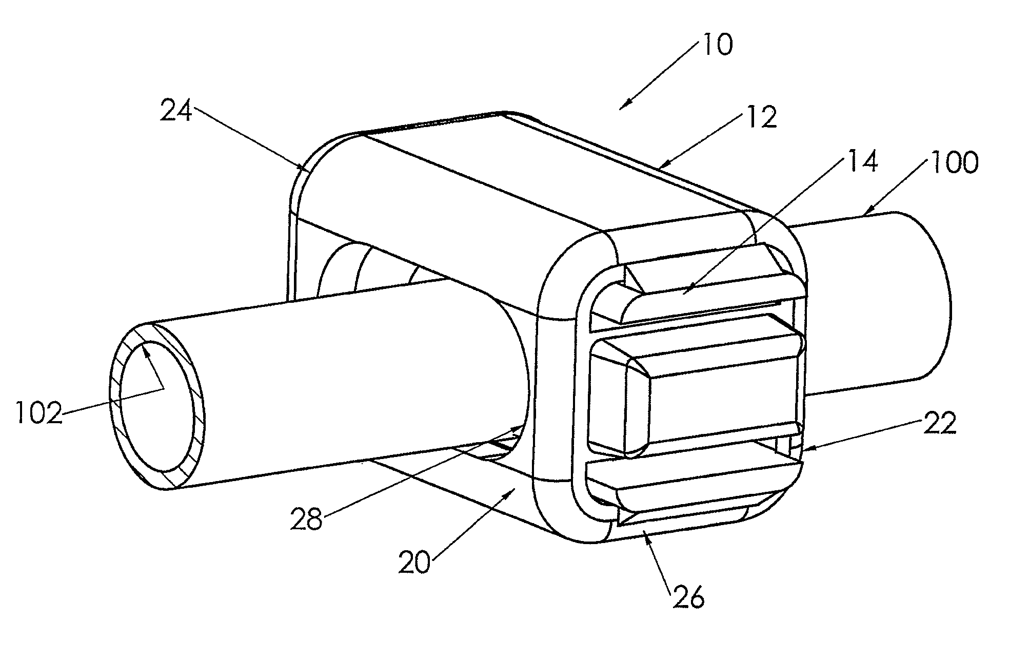
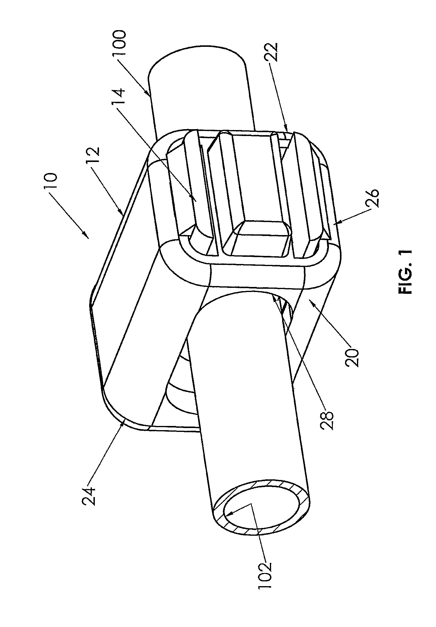
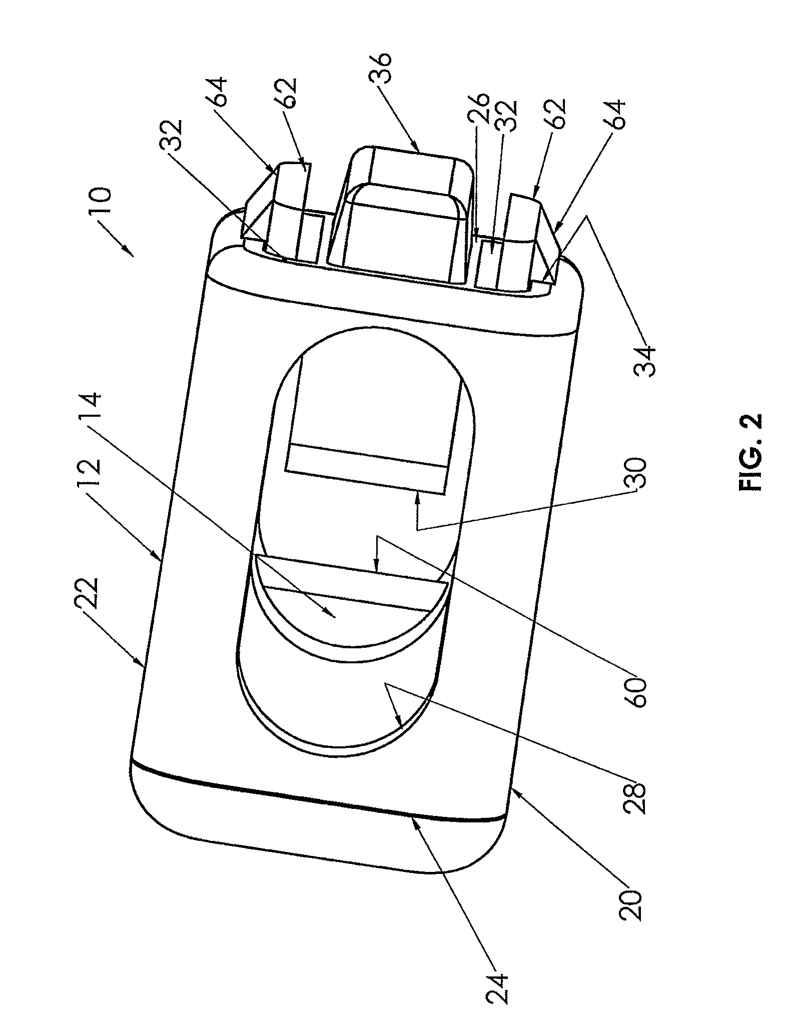
[0029]Certain terminology is used herein for convenience only and is not to be taken as a limitation on the present invention. The embodiments illustrated below are not intended to be exhaustive or to limit the invention to the precise form disclosed, but are chosen and described to best explain the principle of the invention and its application and practical use and to enable others skilled in the art to best utilize the invention. FIGS. 1 to 11 illustrate a first embodiment of clamp assembly of the present invention, FIG. 12 illustrates a second embodiment, and FIGS. 13 to 20 illustrate a third embodiment.

[0030]Clamp assembly 10 of FIGS. 1 to 11 includes two pieces, a housing 12 and a clamp 14. Housing 12 has two side walls 20,22 extending from first end 24 to second end 26, and each side wall includes an opening such that the openings are aligned to define a tubing-receiving channel 28 for flexible tubing 100 having a lumen 102 for fluid flow, shown in FIG. 1. Clamp 14 is slidabl...


PUM


Abstract

A clamp assembly (10,110) for flexible tubing (100), having a housing (12,112) and a clamp (14,114) slidable within the housing between first and second positions, to occlude the tubing when the clamp is in the second position. Both the clamp and the housing include tubing-engaging ribs (30,60;130,160) to compress the tubing when the clamp is moved from its first or open position to its second or occluding position, with the tubing-engaging ribs being axially offset to force the tubing (100) into a tortuous path causing occlusion thereof. A pair of latch arms (62) extend forwardly from the clamp to follow respective channels (32) formed into housing side walls (20,22), with latch arm free ends (64) extending beyond the end of the housing to become latchingly engaged therewith when the clamp is moved into its occluding position, and also to be exposed to be manually engaged for delatching when desired.

Description

CROSS-REFERENCE TO RELATED APPLICATIONS[0001]This application claims the benefit of U.S. Provisional Patent Application Ser. No. 61 / 108,940 filed Oct. 28, 2008.FIELD OF THE INVENTION[0002]This relates to the field of medical devices and more particularly to flexible medical tubing and clamping thereof.BACKGROUND OF THE INVENTION[0003]Catheters may be located in various venous locations and cavities throughout the body of a patient for introduction of fluids to a body or removal of fluids from the body. Such catheterization may be performed by using a single catheter having multiple lumens. A typical example of a multiple lumen catheter is a dual lumen catheter assembly in which one lumen introduces fluid and the other lumen removes fluid. Catheterization may also be performed by using multiple single-lumen catheters, such as TESIO® catheters sold by Medical Components, Inc. of Harleysville, Pa.[0004]Each catheter lumen is typically connected to a distal end of an extension tube via ...

Claims


Application Information

Patent Timeline
Patent Type & Authority Patents(United States)
IPC IPC(8): F16K7/04A61M5/00
CPCA61M39/288
Inventor FISHER, MARK S.WALL, W. SHAUN
Owner MEDICAL COMPONENTS INC
Why Eureka
Try Eureka