Electrical plug connector as fuel injector contact for shakeproof applications

a fuel injector and plug connector technology, applied in the direction of coupling device connection, machine/engine, mechanical apparatus, etc., can solve the problems of affecting the service life of the plug connector, so as to reduce the micromotion, reduce the wear, and reduce the effect of electrical transition resistan

Inactive Publication Date: 2010-10-14
ROBERT BOSCH GMBH
View PDF12 Cites 7 Cited by
  • Summary
  • Abstract
  • Description
  • Claims
  • Application Information

AI Technical Summary

Benefits of technology

[0010]The example plug connector according to the present invention enables allowing wear of <0.2 mm per contact area without the formation of an oxide layer. Since there is no layer, there is no need for the failure criterion of frictional layer wear. By raising the normal contact force per contact area by a factor of 10, it is achieved that the micromotions may be reduced, and consequently wear is reduced. In addition, the quality requir

Problems solved by technology

Relative micromotions, which occur based on vibrations of the components (mounting location) of the wiring harness, lead to wear between the socket contact and the knife blade.
Classical remedial measures against this contact wear that is caused by engine vibrations or temperature changes, i.e., frictional corrosion in the case of tinned systems or wearing through in the case of gold-plated or silver-plated systems, are decoupling elements such as a metallic meander band or a little copper band designed as a looping, which are effective, to be sure, but make the contact more expensive, and which, as a rule, weaken the current-carrying capability (because of the tapering of the cross section) or, in individual cases, even an increased contact normal force in order to improve the response to shaking, the possible variation in the normal force being usually limited by the plastic properties (yield point) of the copper material of the contact springs (lamellae).
If there is no gold surface present, there is an increased risk of an oxide layer forming on the base material, and the contact location (contact/solid conductor) be

Method used


Image

  • Electrical plug connector as fuel injector contact for shakeproof applications
  • Electrical plug connector as fuel injector contact for shakeproof applications
  • Electrical plug connector as fuel injector contact for shakeproof applications

Examples


Embodiment Construction

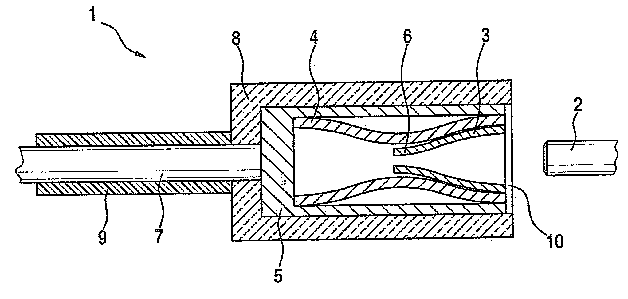
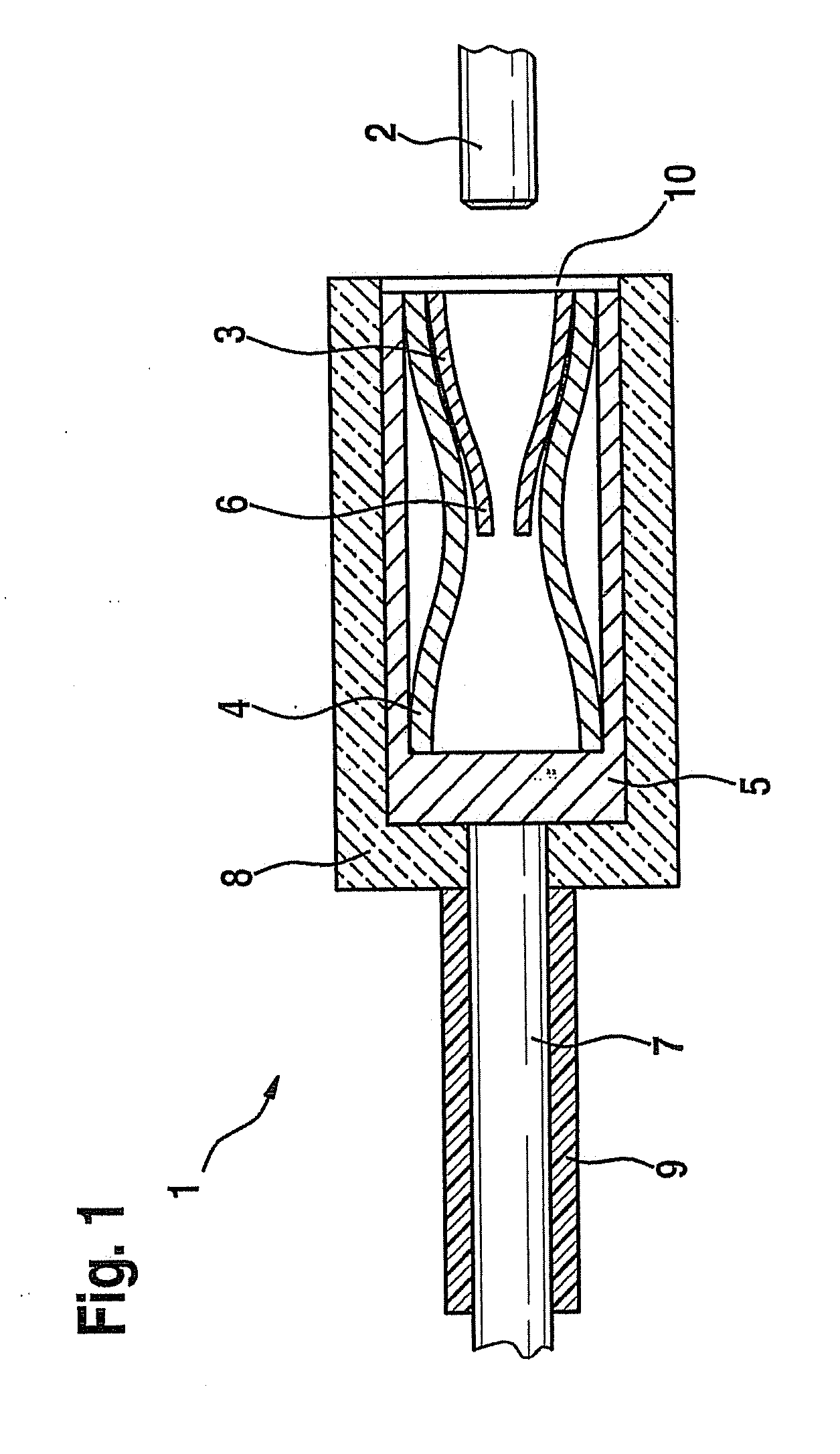
[0021]Electrical plug 1 shown in FIG. 1 is designed as a socket contact or round contact, and is used for the electrical contacting of a pin 2.

[0022]Electrical plug 1 includes an inner contact part 3 for electrically contacting pin 2, an external retention spring 4 that surrounds inner contact part 3, and a metal socket 5. Inner contact part 3 is made of nickel brass, preferably N18 (Wieland trade name), and in the exemplary embodiment shown is developed as a longitudinally slitted round sleeve, which has a plurality of contact fingers (lamellae) 6 that are directed inwards and may be formed by a rolled-up sheet metal part made of nickel brass. Thus, inner contact part 3 has no surface coating, particularly no gold, silver or tin coating. Inner contact part 3 is set tightly in external retention spring 4, which is formed of stainless spring steel (e.g., 1.4310 having a strength of 1500 MPA). External retention spring 4, in turn, is mounted in metal socket 5, made, for instance, of b...


PUM

PropertyMeasurementUnit
Electrical conductivityaaaaaaaaaa

Abstract

In an electrical plug connector in the form of a socket contact, having an inner contact part for the electrical contacting of a pin and having an external retention spring surrounding the inner contact part, the inner contact part is formed of nickel brass.

Description

FIELD OF THE INVENTION[0001]The present invention relates to an electrical plug connector.BACKGROUND INFORMATION[0002]A plug contact that is usual in the automotive field is described in German Patent Application No. DE 102 48 809 A1.[0003]An electrical plug connector in the form of a vibration-stressed socket contact for producing an electrical plug connection in the motor vehicle field is described in German Patent Application No. DE 102 48 809 A1. The electrical plug connector is made up of an inner contact part and an external retention spring. The inner part itself includes contact lamellae, which rest against a mating component, preferably a knife blade, at a contact point. In order to ensure increased contact security by an optimum normal contact force for each contact lamella, even in the case of slanting or vibrating or wobbling mating components, the inner contact part has at least three guiding contact lamellae, each of the contact lamellae having at least one contact poi...

Claims


Application Information

Patent Timeline
IPC IPC(8): B05B15/00H01R13/18
CPCF02M51/005H01R13/03C22C9/06H01R13/18C22C9/02H01R13/111
Inventor TEKORAL, REFIK ALPREHBEIN, PETERTENA, SABAS ROMANFLEIG, MICHAEL
Owner ROBERT BOSCH GMBH
Why Eureka
Try Eureka