Temporary vascular filters

a filter and vascular technology, applied in the field of vascular filters, can solve the problems of inconvenient use of permanent filter devices, inconvenient removal of current filter devices, and patient risk of pulmonary embolism, so as to achieve easy or safe removal, reduce risk, and easy

Inactive Publication Date: 2006-12-12
DUKE UNIV
View PDF5 Cites 80 Cited by
  • Summary
  • Abstract
  • Description
  • Claims
  • Application Information

AI Technical Summary

Benefits of technology

[0004]Temporary immobilization and a number of medical procedures subject the patient to the risk of pulmonary embolism. This risk can be significantly reduced by the use of a filter implant. Currently available filter devices are not easily or safely removable after they have remained in place for more than

Problems solved by technology

Temporary immobilization and a number of medical procedures subject the patient to the risk of pulmonary embolism.
Currently available filter devices are not easily or safely removable after they have remai

Method used


Image

  • Temporary vascular filters
  • Temporary vascular filters
  • Temporary vascular filters

Examples


Embodiment Construction

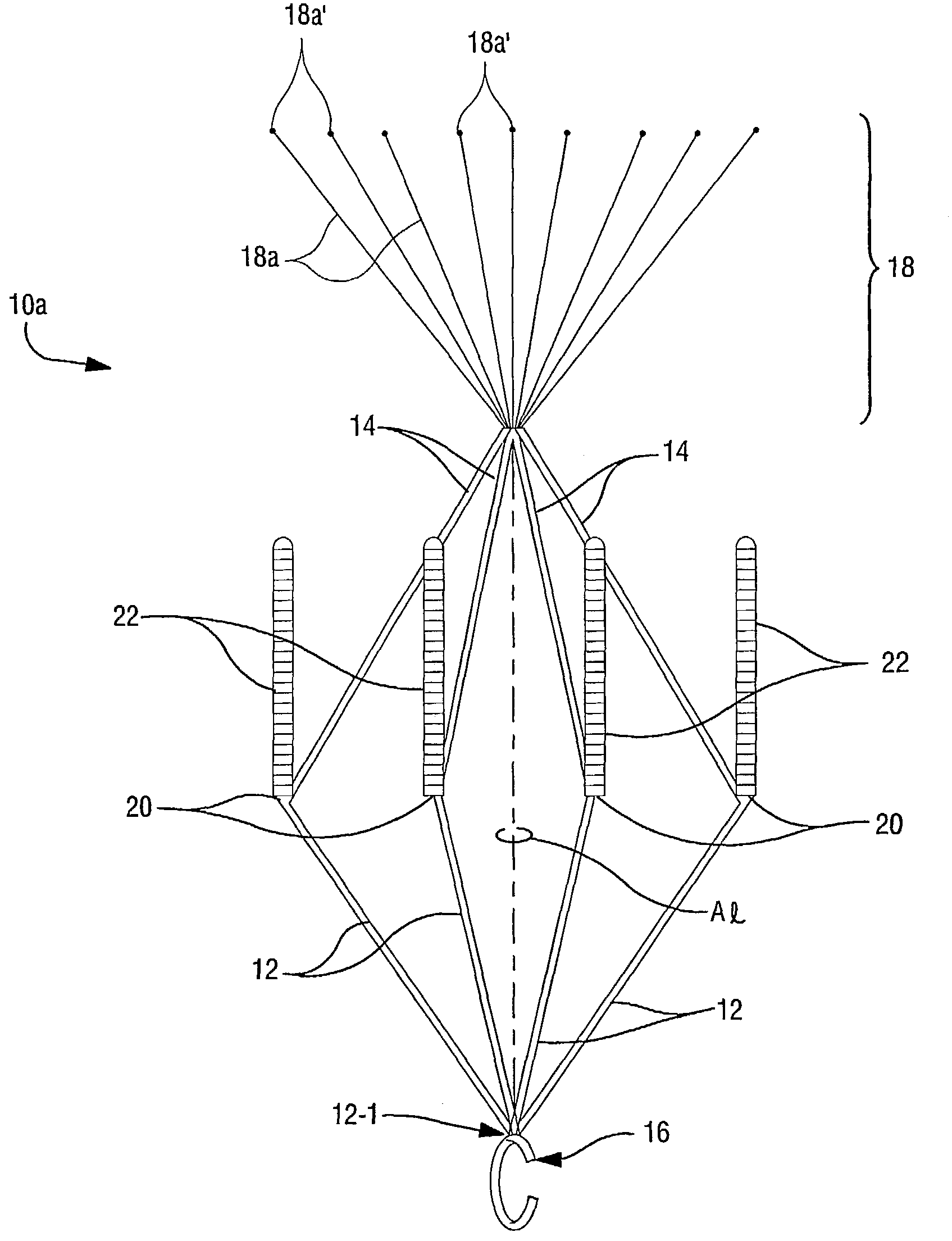
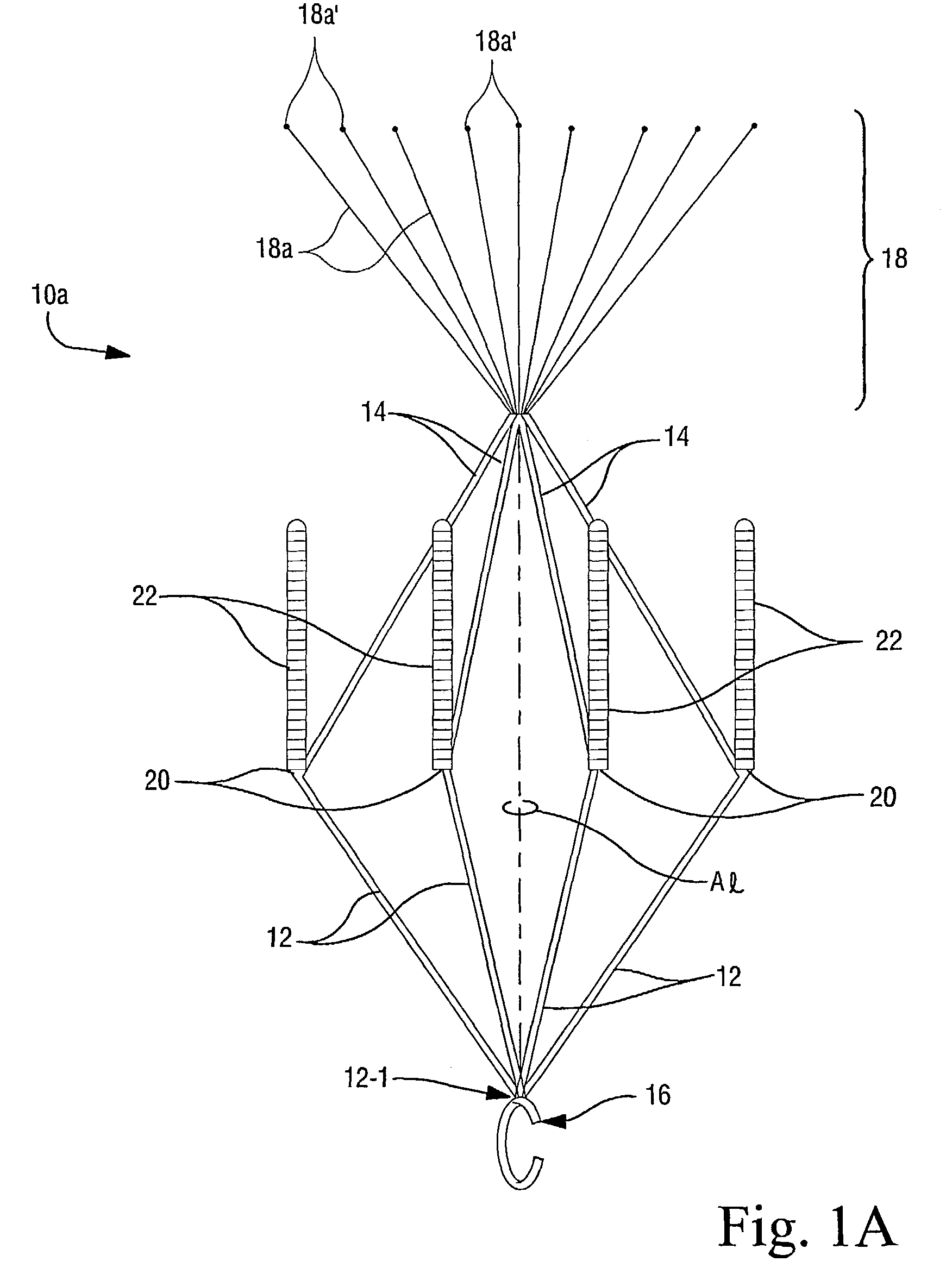
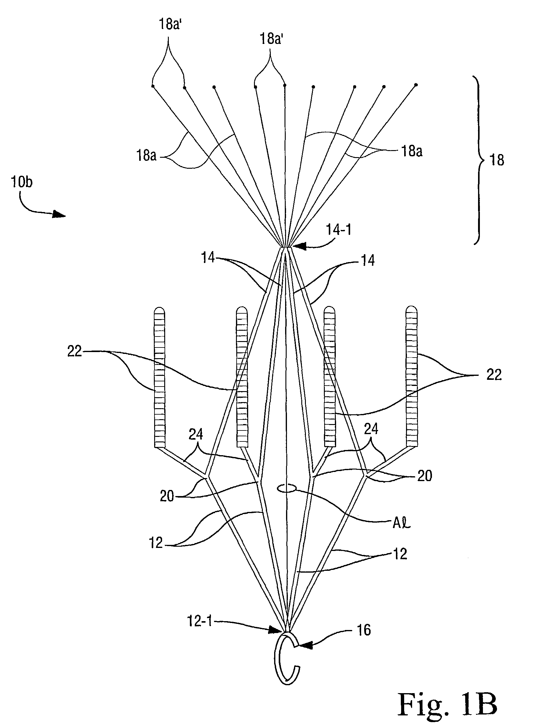
[0019]Preferred vascular filters 10a, 10b in accordance with the present invention are shown in accompanying FIGS. 1A and 1B, respectively, as including paired proximal and distal support arm portions 12, 14 which, in the expanded configuration shown in FIGS. 1A and 1B, radiate divergently from the elongate axis Al of the filters 10a, 10b. The angle between these proximal and distal support arm portions 12, 14 is most preferably about 135°+ / − when the filter 10a, 10b is in its expanded configuration. As will be discussed in greater detail below, a hook 16 is provided at the proximal juncture 12-1 of the proximal support arm portions 12, 14.

[0020]The blood filter devices 10 of this invention are provided with a distal blood-filtering portion 18. More specifically, the distal juncture 14-1 of the distal support arm portions 14 is most preferably attached to the proximal end of a plurality of filter arms (a few if which are identified by reference numeral 18a in FIGS. 1A and 1B). These...


PUM

PropertyMeasurementUnit
Lengthaaaaaaaaaa
Hydrolysableaaaaaaaaaa
Bioabsorbableaaaaaaaaaa

Abstract

Blood filters (10a, 10b) sized and configured to be positioned within a vascular vessel include a plurality of anchoring arms (22) having a removable sleeve (22-2) for temporarily anchoring the blood filter to a vessel wall. In especially preferred embodiments, the removable sleeve (22-2) is formed of bioabsorbable material. When the filter (10a, 10b) is deployed, it is this removable sleeve (22-2) which comes into contact with the inner tissue wall of the patient's blood vessel (typically the inferior vena cava). When it is desired to remove the filter, endothelization of the sleeve (22-2) has typically occurred but since the sleeves are a removable (separable) component part of the anchoring arms (22), the entire filter device (10a, 10b) can be retrieved thereby leaving the endothelized sleeves (22-2) remaining in place on the interior wall of the patient's vascular vesse. However, such sleeves (22-2) will be absorbed over time (preferably by means of hydrolysis) since they are formed of a bioabsorbable polymeric material. In such a manner, the filters (10a, 10b) of the present invention allow relatively easy retrieval while minimizing (if not preventing entirely) harm to the vascular endothelium.

Description

[0001]This application is the US national phase of international application PCT / US01 / 23868 filed 30 Jul. 2001 which designated the U.S.CROSS-REFERENCE TO RELATED APPLICATION[0002]This application is based on, and claims domestic priority benefits under 35 USC §119(e) from, U.S. Provisional Application Ser. No. 60 / 223,190 filed on Aug. 4, 2000, the entire content of which is expressly incorporated hereinto by reference.FIELD OF THE INVENTION[0003]The present invention relates generally to the field of vascular filters, especially thrombus blood clot filters, and methods. More specifically, the present invention relates to temporary (removable) emobolus blood clot filters and methods especially useful for placement in a patient's inferior vena cava (IVC).BACKGROUND AND SUMMARY OF THE INVENTION[0004]Temporary immobilization and a number of medical procedures subject the patient to the risk of pulmonary embolism. This risk can be significantly reduced by the use of a filter implant. Cu...

Claims


Application Information

Patent Timeline
IPC IPC(8): A61M29/00A61F2/00A61F2/01A61F2/02A61F2/06
CPCA61F2/01A61F2/848A61F2002/011A61F2002/016A61F2210/0004A61F2250/0071A61F2230/005A61F2230/0067A61F2230/0078A61F2/011A61F2/0103A61F2/0105
Inventor THOMAS, JOHN
Owner DUKE UNIV
Why Eureka
Try Eureka