Apparatus and method for detecting objects located on an airport runway

a technology for airport runways and objects, applied in the direction of aircraft traffic control, burglar alarm short radiation actuation, instruments, etc., can solve the problems of aircraft damage, aircraft death, aircraft damage, etc., and not eliminate the hazard of unseen objects on the runway

Inactive Publication Date: 2006-12-12
DERRINGER BYRON SCOTT
View PDF39 Cites 22 Cited by
  • Summary
  • Abstract
  • Description
  • Claims
  • Application Information

AI Technical Summary

Benefits of technology

[0014]An object of the present invention is to provide a novel apparatus and method that can detect objects or other debris on an airport runway surface and provide an early warning signal to the aircraft, air traffic control, and / or ground based personnel.
[0015]An object of the present invention is to provide a novel apparatus and method that can provide information to the aircraft, air traffic control, and / or ground based personnel prior to aircraft landing and takeoff, thus providing time for corrective action to clear the airport runway surface prior to landing and takeoff. Air traffic control and ground based personnel may be provided with prior knowledge of objects or other debris prior to aircraft touch down on the airport runway surface.
[0016]An object of the present invention is to provide a novel apparatus and method that may direct one or more laser beams across an airport runway surface that may contain objects or other debris. As a result of the novel apparatus, the invention can provide a sufficient period of time for the aircraft, air traffic control, and / or ground based personnel to take corrective action to avoid the hazardous conditions.
[0029]In accordance with a preferred embodiment of the present invention, the plurality of optical laser apparatus are arranged such that their detection regions are distributed in partially overlapping orientation in azimuth fashion, thereby covering the airport runway surface. Preferably, the optical laser transmission and receiving apparatus also includes apparatus for comparing the outputs of more than one of the plurality of optical laser relating to a given object in order to define the angular position of the object with enhanced resolution.
[0038]In accordance with a preferred embodiment of the present invention, the auxiliary non-optical laser system or other debris sensing step may include a laser energy transmission and reception step. Preferably, the optical laser sensing step includes comparing the outputs of more than one of a plurality of optical-lasers relating to a given object in order to define the angular position of the object with enhanced resolution.
[0047]There are three additional advantages of the embodiments of the present invention: 1. the use of the optical laser apparatus and method allows detection of objects and other objects or other debris in weather where visibility is very low (i.e. fog or any other type of inclement weather or adverse condition), 2. the use of the method with transceiver to reflector will be more cost effective in construction based on the expense of reflectors versus receivers, and 3. prevention / warning of incursion of other aircraft within the same space.

Problems solved by technology

There have been repeated catastrophes associated with objects or other debris on airport runway surfaces involving deaths of thousands of people and damage to aircraft.
Aircraft are operated by pilots often unfamiliar with individual airports and runways, and possibly without adequate visibility during take off or landing.
Even the presence of air traffic control does not wholly eliminate the hazard of unseen objects on the runway to the aircraft and its passengers.
French investigators indicated that “a 16-inch piece of metal on the runway had burst the tire, setting off the sequence of apparently freakish events that caused the plane to crash within 90 seconds” after takeoff.
In fact, it has been said that “objects or other debris on the runway [is] most often the problem” in catastrophes when aircraft are landing and taking off.
Apparently, this is a common mistake due to location of the pilot in the aircraft, the familiarity of the pilot with the airport, or other visibility issues.
However, despite this prior public knowledge, Applicant is unaware of any known, proposed, or successfully implemented sensing systems for detecting objects or other debris on an airport runway surface which would provide an advance warning to air traffic control and airport ground based personnel.

Method used


Image

  • Apparatus and method for detecting objects located on an airport runway
  • Apparatus and method for detecting objects located on an airport runway
  • Apparatus and method for detecting objects located on an airport runway

Examples


example 1

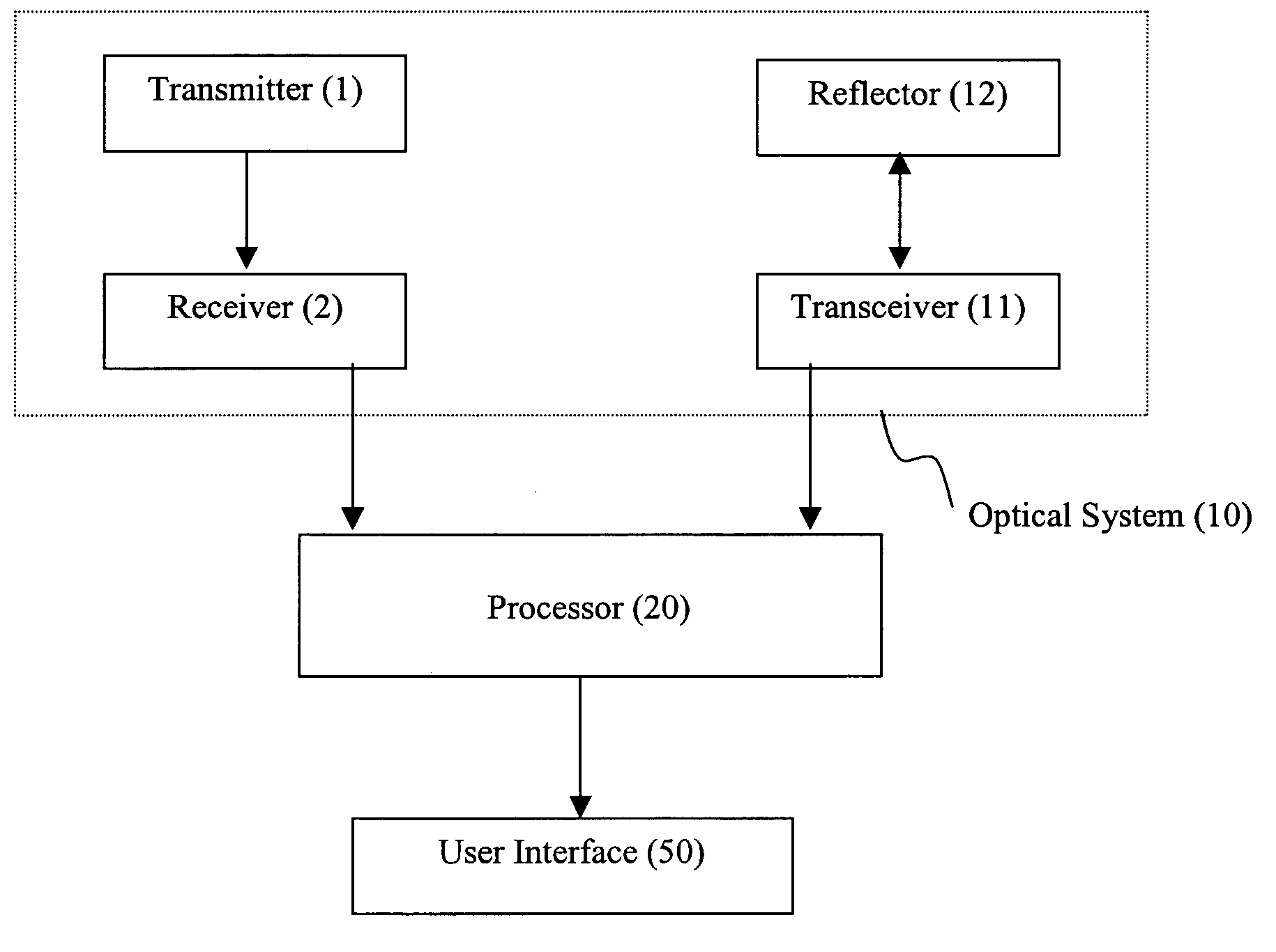
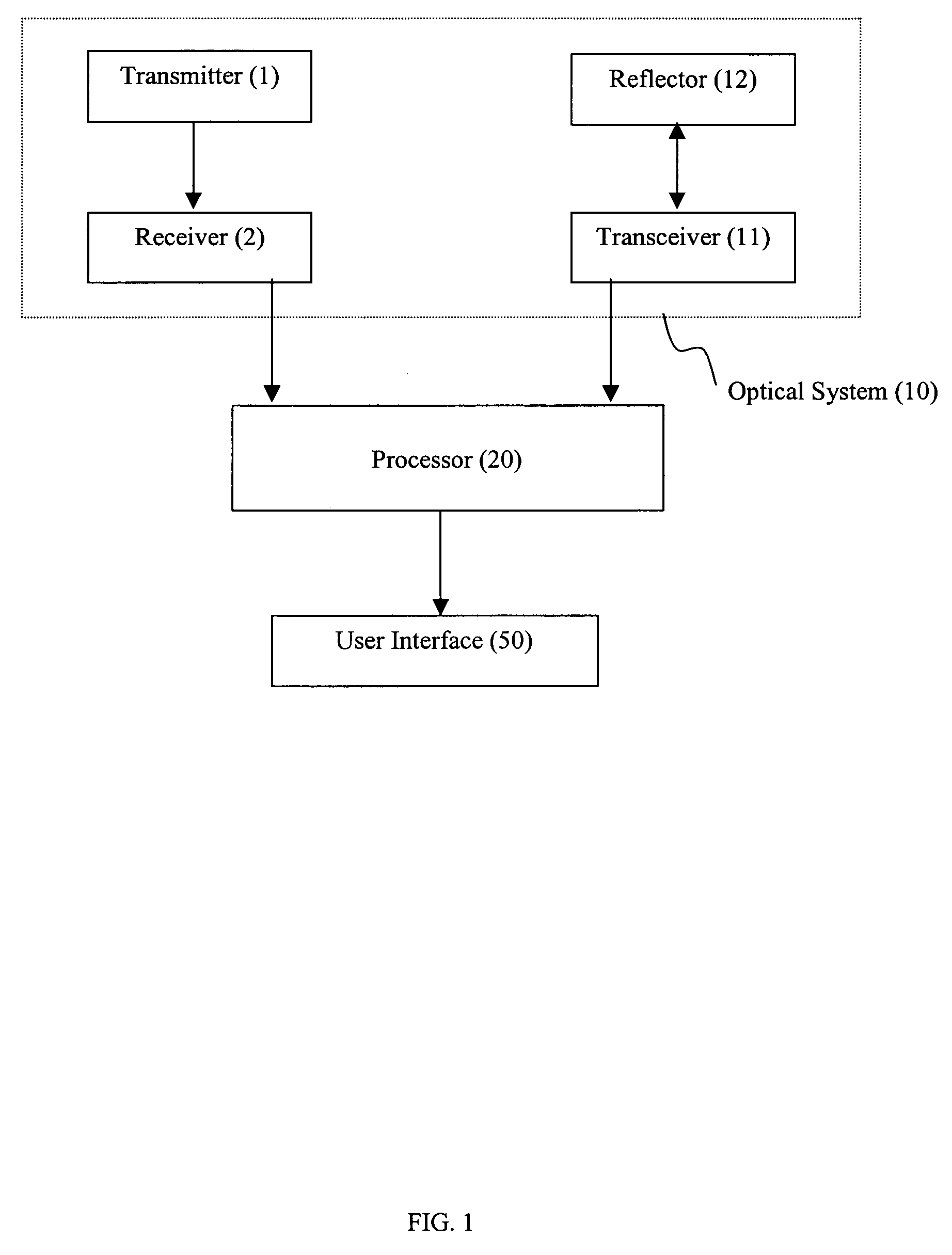
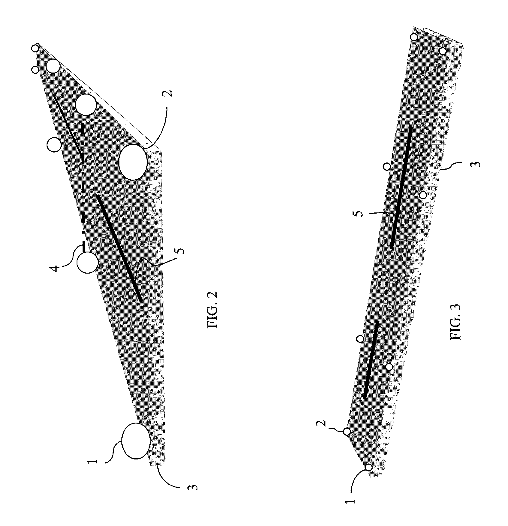
[0115]Reference is now made to FIG. 2 illustrating a 3-dimensional frontal view of the airport runway surface 3, with the center line 5 marking the width in an equal distance to both edges of the airport runway surface 3. The optical laser transmitter 1 which supplies the optical laser 4 to the optical laser receiver 2 is preferably located at the edge of the airport runway surface 3.

[0116]In the different configurations of embodiments that follow, transmitter 1 can also be used as a transceiver 11 with respect to receiver 2 and reflector 12. The location of the optical laser receiver 2 can be located on the opposite side facing back in the direction of the optical laser transmitter 1. Both the optical laser transmitter 1 and optical laser receiver 2 are positioned along the width down the length of the entire airport runway surface 3.

[0117]FIG. 3 illustrates the side view of a 3-dimensional airport runway surface 3 with the center line 5 marking the width in an equal distance to bo...

example 2

[0118]FIG. 4 illustrates a top view of the airport runway surface 3 with optical laser transceivers 11 and optical laser reflectors 12 on opposite sides of the airport runway surface 3. This configuration illustrates the arrangement of the optical laser 4 as magnified in FIG. 4A, which shows the configuration covering the width of the runway area specified. The optical laser 4 may be constantly traveling through several different planes while passing over the width of the airport runway surface 3.

[0119]FIG. 5 illustrates a top view of the airport runway surface 3 showing the location of optical laser transmitters 1 on one side of the airport runway surface 3, and optical laser receivers 2 on the opposite side. The laser beam 4 as magnified in FIG. 5A illustrates the configuration covering the width of the area specified showing the direction from one side to the other and constantly traveling through several different planes.

example 3

[0120]FIG. 6 is a top view of the airport runway surface 3 with optical laser transceivers 11 located on each end of the airport runway surface 3 on the center line 5 marking the width in an equal distance to both edges. Optical laser reflectors 12 are present on both sides of the runway surface 3 covering the length and width of area specified by reflecting optical lasers 4 from optical laser transceivers 11 in different directions, for example, three different directions, while constantly traveling through several different planes.

[0121]FIG. 6A is a simplified top view of the airport runway surface 3 illustrating where optical lasers 4 provide protection for aircraft within landing and take off sections 9 of the airport runway surface 3.


PUM


Abstract

An apparatus for detecting objects on an airport runway. The apparatus comprises a first transmitter adapted to be positioned adjacent to the runway, a first receiver adapted to be positioned adjacent to the runway, a processor operably linked to the first receiver, and a user interface operably linked to the processor. The first transmitter is adapted to emit a first beam of light across the runway to the first receiver and the first receiver is adapted to send a first indication to the processor if the first beam of light is interrupted by an object on the runway. The processor is adapted to send a warning indication to the user interface in response to the first indication and the user interface is adapted to generate a warning upon receipt of the warning indication.

Description

CROSS REFERENCE TO RELATED PATENT APPLICATION[0001]This application is a continuation-in-part of, and claims priority on, U.S. patent application Ser. No. 09 / 742,540 for METHOD AND APPARATUS FOR WARNING AND DETECTING DEBRIS LOCATED ON AIRPORT RUNWAY SURFACE, filed on Dec. 22, 2000 now abandoned.FIELD OF THE INVENTION [0002]The present invention relates to an apparatus and method for detecting objects located on an airport runway. More particularly, the present invention is an apparatus and method employing optical transmitters, transceivers, receivers, reflectors, and various processing means for detecting objects located on an airport runway.BACKGROUND OF THE INVENTION[0003]The problems associated with objects located on airport runway surfaces during aircraft landing and take off have long been recognized. There have been repeated catastrophes associated with objects or other debris on airport runway surfaces involving deaths of thousands of people and damage to aircraft. Aircraft...

Claims


Application Information

Patent Timeline
Patent Type & Authority Patents(United States)
IPC IPC(8): G08G5/04G08B13/184
CPCG08B13/184G08G5/0026G08G5/0082G08G5/0091
Inventor DERRINGER, BYRON SCOTT
Owner DERRINGER BYRON SCOTT
Why Eureka
Try Eureka