

Interactive multimedia for remote diagnostics and maintenance of a multifunctional peripheral
a multifunctional peripheral and multimedia technology, applied in the field of multifunctional peripherals, can solve problems such as problems such as problems such as problems such as problems such as problems such as problems such as problems such as problems such as problems such as problems such as problems such as problems such as problems such as problems such as problems such as problems such as problems such as problems such as problems such as problems such as problems such as problems such as problems such as problems such as problems such as problems such as problems such as problems such as problems such as multifunctional peripheral
- Summary
- Abstract
- Description
- Claims
- Application Information
AI Technical Summary
Benefits of technology
Problems solved by technology
Method used
Image

Examples
Embodiment Construction
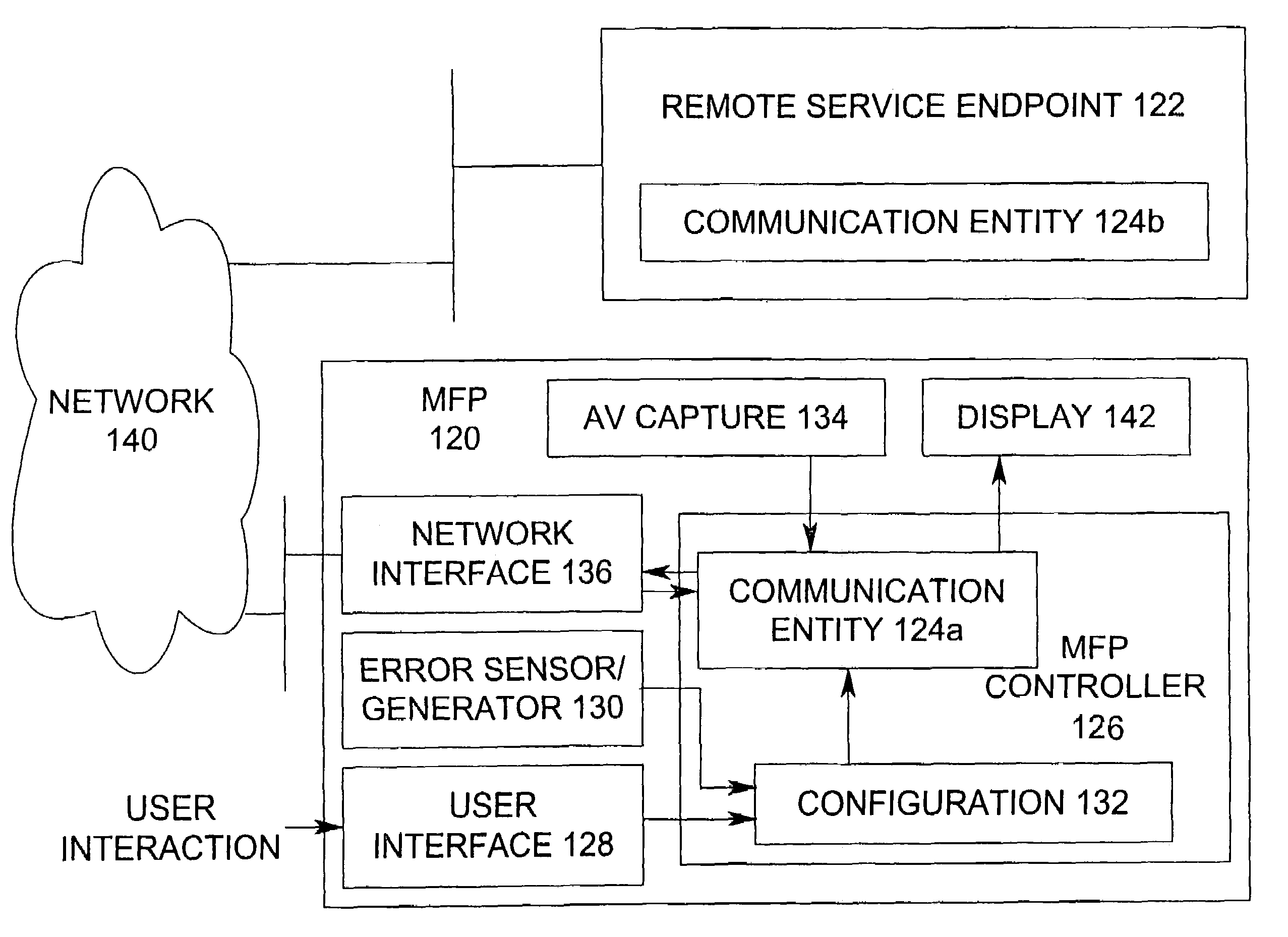
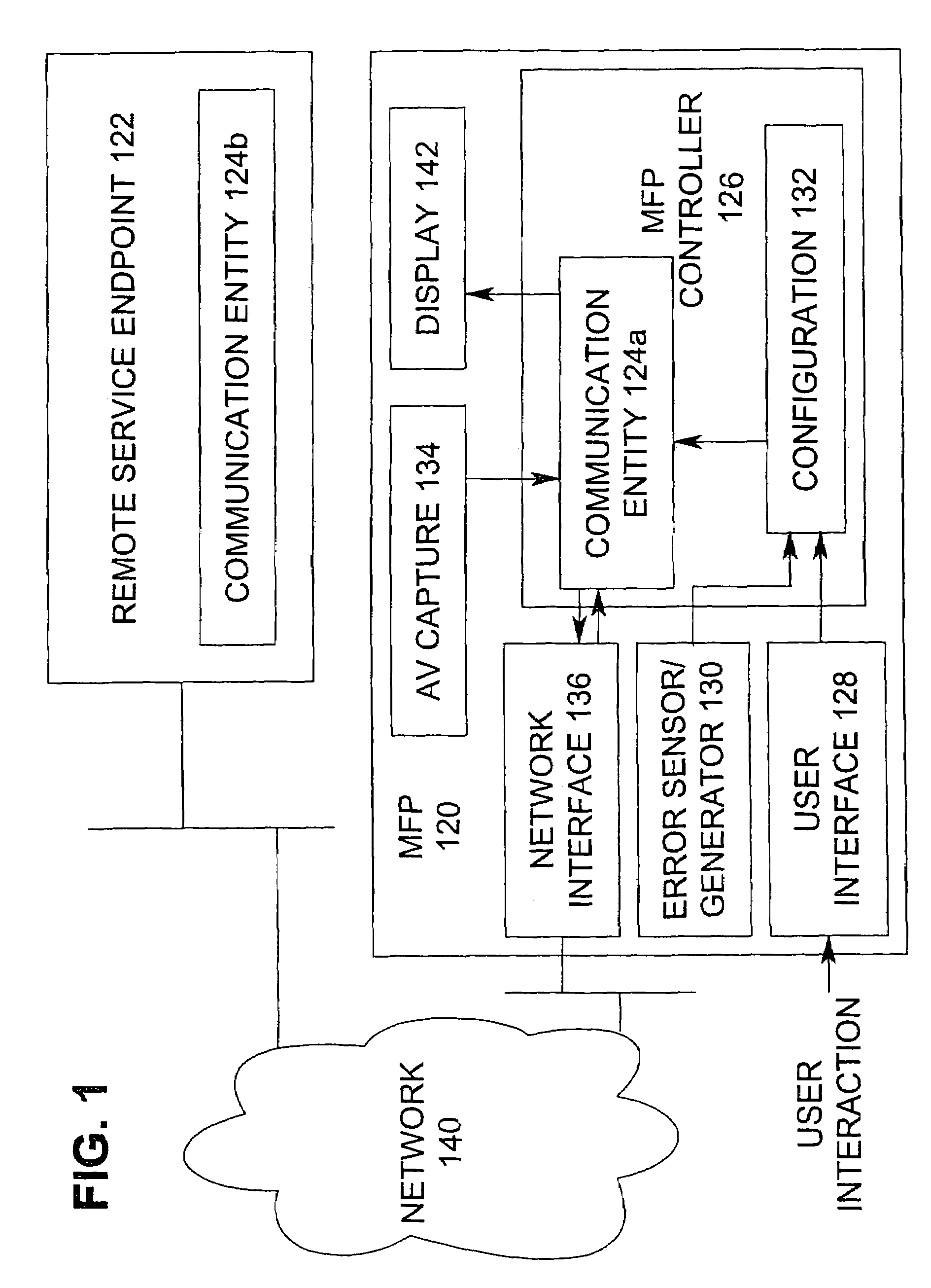
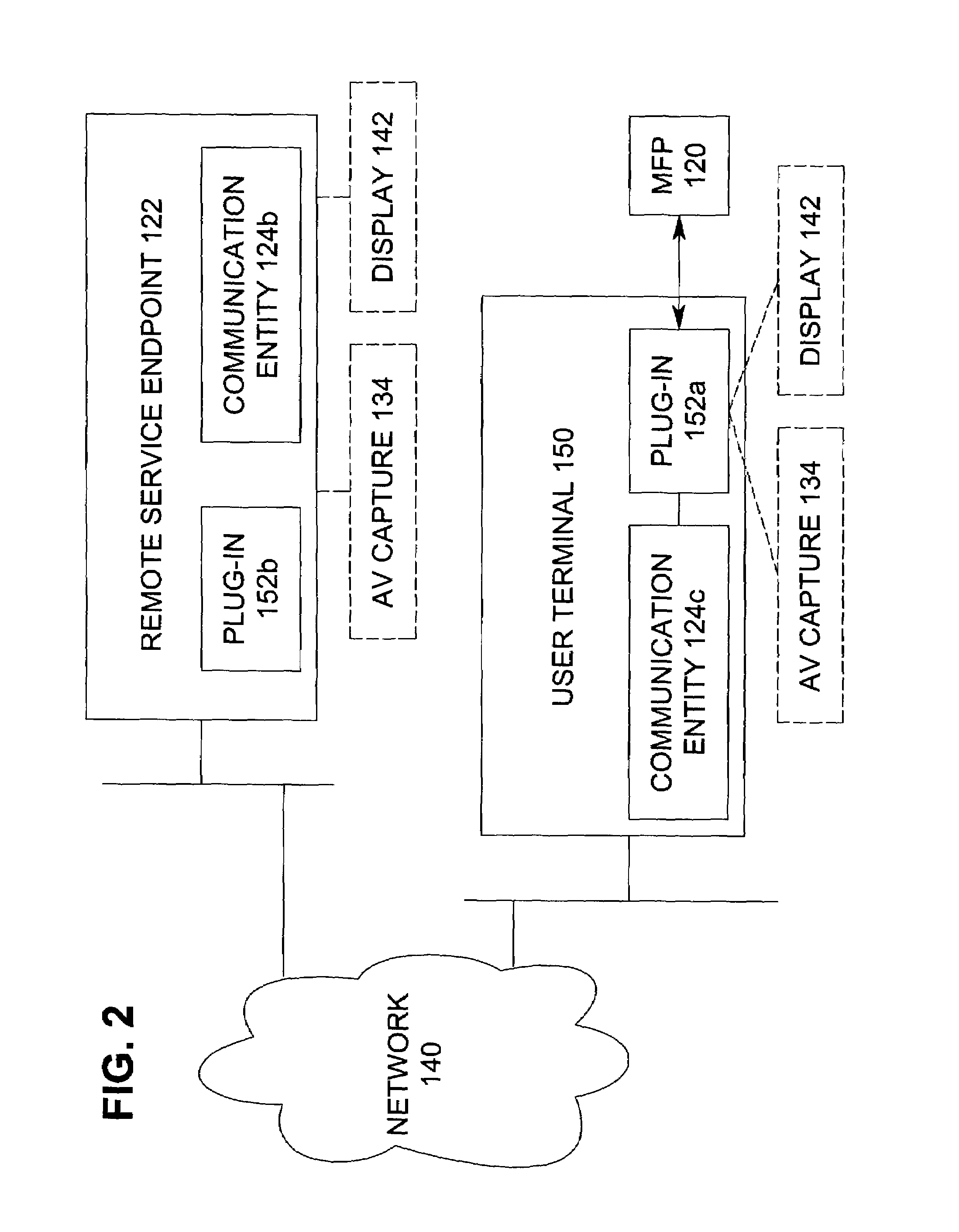
[0025]The present invention is directed to multifunction peripheral and more particularly to a multifunction peripheral configured for supporting real-time interactive multimedia (audio, video, data, and / or control signals) for remote diagnostics, maintenance, and assistance. The present invention recognizes that even if a user is capable of providing a remote service technician with an acceptable level of detail, prior art multifunction peripherals do not allow the user to provide the remote service technician with real time diagnostic sensor data, sounds produced by the machine (which may indicate a failed component), or images of components (which may show signs of wear).
[0026]Using the present invention, the remote service technician can: (1) remotely access the multifunction peripheral; (2) acquire diagnostic data; (3) hear the multifunction peripheral in operation; (4) see the inner workings of the multifunction peripheral; (5) speak with the user at the multifunction peripher...
PUM
 Abstract
Description
Claims
Application Information