Building exhaust and air conditioner condensate (and/or other water source) evaporative refrigerant subcool/precool system and method therefor

a technology of building exhaust and air conditioner condensate, which is applied in the direction of ventilation systems, heating types, domestic cooling apparatus, etc., can solve the problems of low efficiency deviating from the ideal cycle of actual refrigeration, and high cost of subcooling and/or precooling and/or postheating, etc. , to achieve the effect of increasing the refrigeration effect, reducing power consumption, and increasing the pumping efficiency

Inactive Publication Date: 2006-12-19
OLIVE TREE PATENTS 1
View PDF17 Cites 41 Cited by
  • Summary
  • Abstract
  • Description
  • Claims
  • Application Information

AI Technical Summary

Benefits of technology

[0043]Moreover, this present invention may be configured by means of a second apparatus that satisfies the need for lower power consumption, increased pumping efficiency of the compressor, as well as improving the primary condensers performance by means of increased hot gas refrigerant precooling accomplished by utilizing the cold, dry exhaust air required for clean air operation of a building's air supply only or alternatively using the building exhaust air or outdoor air supply and the air conditioning or heat pump systems condensate (or other) water supply to accomplish this precooling conductively or alternatively evaporatively or after first use in the subcooler of the first apparatus. Another alternative would be to precool the hot gas conductively with the cooler and higher humidity air being discharged from the evaporatively cooled subcooler.

Problems solved by technology

However, the actual refrigeration cycle may deviate from the ideal cycle primarily because of pressure drops associated with fluid flow and heat transfer to or from the surroundings.
However, these known methods and devices have drawbacks.
The drawbacks include the high cost of accomplishing the subcooling and / or precooling and / or postheating, and / or the ineffectiveness or degrading effectiveness of the subcooling and / or precooling and / or posting method and / or device.

Method used


Image

  • Building exhaust and air conditioner condensate (and/or other water source) evaporative refrigerant subcool/precool system and method therefor
  • Building exhaust and air conditioner condensate (and/or other water source) evaporative refrigerant subcool/precool system and method therefor
  • Building exhaust and air conditioner condensate (and/or other water source) evaporative refrigerant subcool/precool system and method therefor

Examples


Embodiment Construction

that follows is offered so that the present contribution to the art can be more fully appreciated. Additional features of the invention will be described hereinafter. These form the subject of the claims of the invention. It should be appreciated by those skilled in the art that the conception and the disclosed specific embodiment may be readily utilized as a basis for modifying or designing other structures for carrying out the same purposes of the present invention. It should also be realized by those skilled in the art that such equivalent constructions do not depart from the spirit and scope of the invention as set forth in the appended claims.

BRIEF DESCRIPTION OF THE DRAWINGS

[0049]For a more succinct understanding of the nature and objects of the present invention, reference should be directed to the following detailed description taken in connection with the accompanying drawings in which:

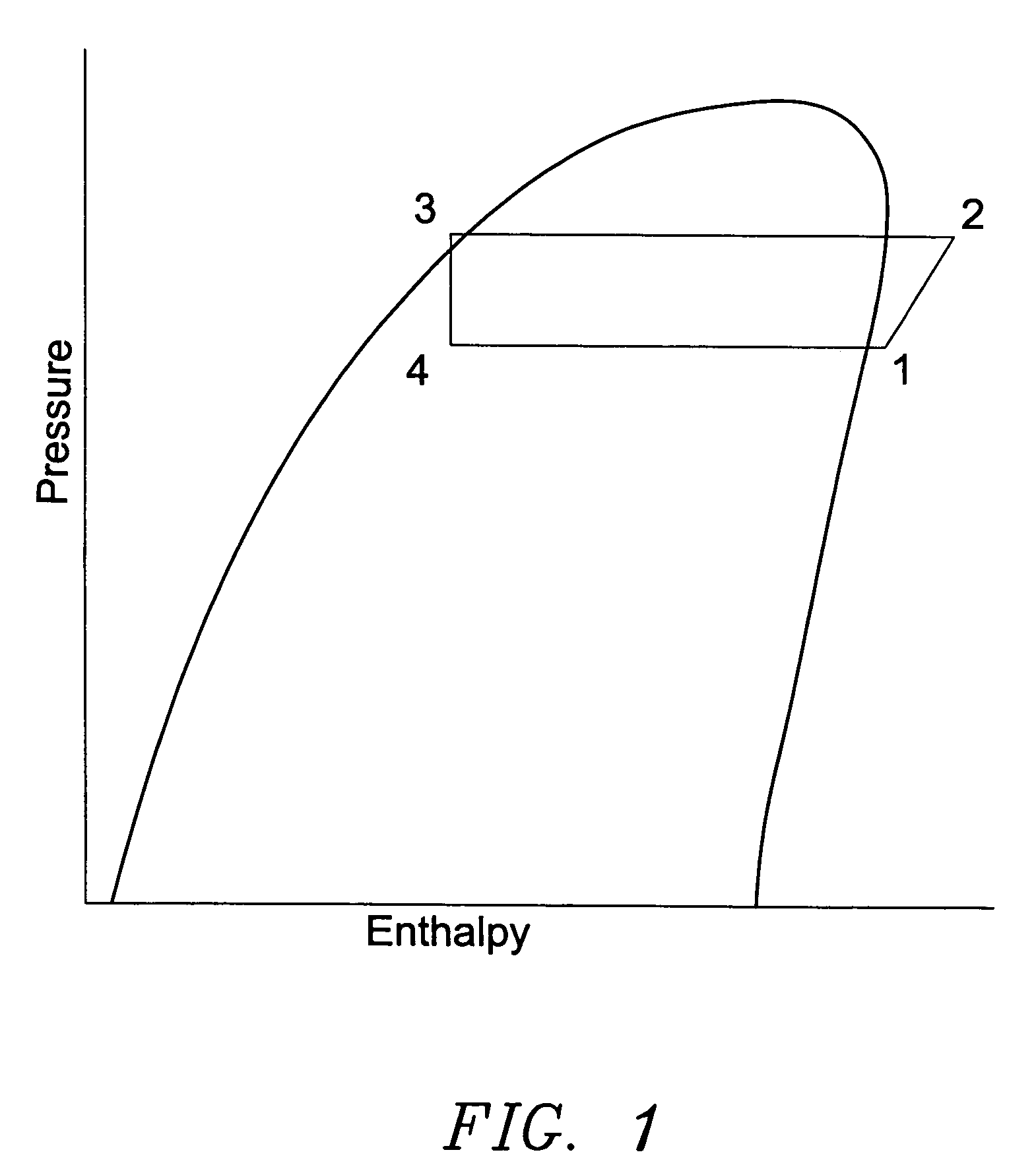
[0050]FIG. 1 is a representation of the refrigeration process on a pressure enthalpy diag...


PUM


Abstract

A system for providing liquid refrigerant subcooling by means of evaporative cooling utilizing the condensate water of said air conditioner, refrigeration / heat pump system and / or other water supply to wet the surface of the subcool heat exchanger and pass the dry exhaust air across the wetted surface of the subcool heat exchanger. A system for providing hot gas discharge refrigerant precooling into the primary condenser of an air conditioner, refrigeration or heat pump system by evaporative cooling utilizing the condensate water of said system and / or other water supply to wet the surface of the precool heat exchanger and then passing the cold, dry exhaust air across the wetted surface of the precool heat exchanger. A combination subcooler / precooler system where the cold dry building exhaust air is used to evaporatively subcool the liquid refrigerant in the water wetted (or dry) subcooler and then used to conductively cool the hot gas refrigerant.

Description

CROSS-REFERENCE TO RELATED APPLICATIONS[0001]The present invention is a continuation-in-part of application Ser. No. 10 / 713,768, filed Nov. 13, 2003, now U.S. Pat. No. 6,857,285 which is a continuation of application Ser. No. 10 / 031,275 filed Nov. 7, 2001 now abandoned, which is a 371 application of PCT / US99 / 23394 filed Oct. 7, 1999, which is a continuation-in-part of application Ser. No. 09 / 168,822, filed Oct. 8, 1998, now U.S. Pat. No. 6,070,423, the disclosures of which are hereby incorporated by reference herein.BACKGROUND OF THE INVENTIONField of the Invention[0002]The present invention relates to a subcool and / or precool system for the liquid refrigerant and / or hot gas discharge refrigerant of an air conditioning, refrigeration or heat pump system (cooling mode) that utilizes either the exhaust air required for clean air operation of a building's conditioned air supply only, or the exhaust air and the condensate discharge from said air conditioning, refrigeration or heat pump ...

Claims


Application Information

Patent Timeline
Patent Type & Authority Patents(United States)
IPC IPC(8): F25D23/06F24F1/0063F24F12/00F24F13/22F25B6/04F25B40/00F25B40/02F25B40/06F25D3/02F25D23/12F28D5/00
CPCF24F12/006F24F13/222F25B40/00F25B40/02F24F2001/0092F24F2013/225Y02B30/563F25B40/06Y02B30/545F25B6/04F24F1/0007Y02B30/56F24F1/0063Y02B30/54
Inventor HERBERT, THOMAS H.
Owner OLIVE TREE PATENTS 1
Why Eureka
Try Eureka