Diaphragm pump with a crinkle diaphragm of improved efficiency

a diaphragm pump and efficiency technology, which is applied in the direction of flexible member pumps, machines/engines, positive displacement liquid engines, etc., can solve the problems of reducing the stroke and reducing the vibration generated by the actuator, so as to improve the efficiency of diaphragm motion, shorten the stroke of the movable mass, and improve the effect of coupling

Active Publication Date: 2014-05-06
AMS R&D
View PDF6 Cites 30 Cited by
  • Summary
  • Abstract
  • Description
  • Claims
  • Application Information

AI Technical Summary

Benefits of technology

[0007]In order to achieve this object, there is provided a pump having an undulating diaphragm mounted on a support for undulating between two end plates under drive from at least one electromagnetic actuator in order to transfer a fluid between an inlet of the pump and an outlet of the pump. According to the invention, the pump includes adapter means connecting the diaphragm support to a movable portion of the actuator in order to shorten the stroke of the movable mass of the actuator such that its stroke is shorter than the stroke of the diaphragm support.
[0008]Such a reduction in the stroke of the movable portion of the actuator serves to improve coupling between the undulating diaphragm and the fluid, to improve the effectiveness of diaphragm motion by optimizing its reaction force, and thus to improve propulsion efficiency. In the actuator, it enables the operating frequency to be increased, and reduces the mechanical losses associated with friction and viscous losses. And naturally, reducing the stroke contributes to diminishing the vibration generated by the actuator and to which the pump is subjected. This reduction also makes it possible to increase the force / mass ratio, thereby making it possible to reduce kinetic losses associated with the movement of the masses, and thus to increase the overall efficiency of the pump. These improvements lead to better efficiency for the pump head and to an actuator that is more compact.

Problems solved by technology

And naturally, reducing the stroke contributes to diminishing the vibration generated by the actuator and to which the pump is subjected.

Method used


Image

  • Diaphragm pump with a crinkle diaphragm of improved efficiency
  • Diaphragm pump with a crinkle diaphragm of improved efficiency
  • Diaphragm pump with a crinkle diaphragm of improved efficiency

Examples


Embodiment Construction

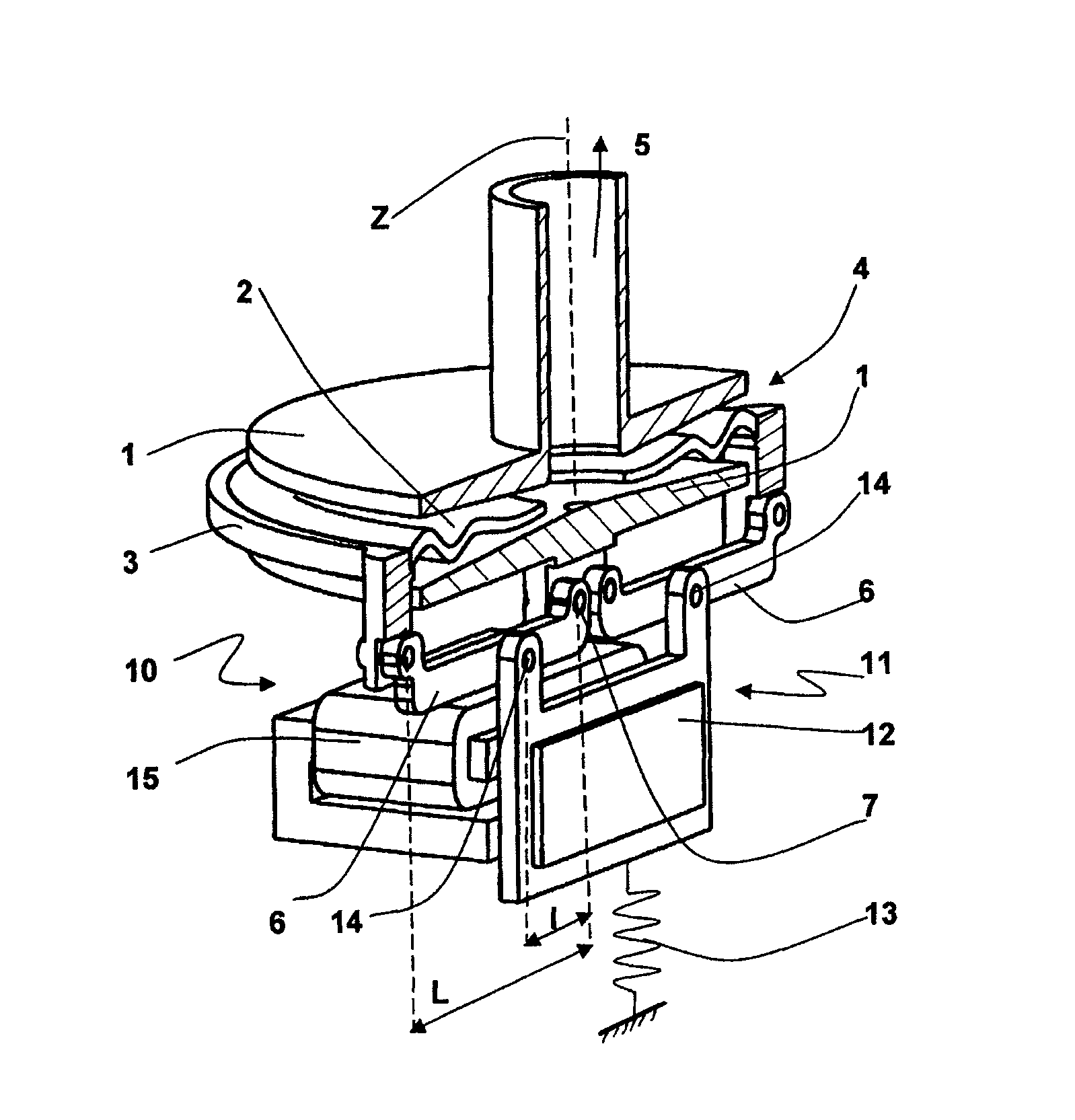
[0016]With reference to FIG. 1, and according to a first implementation principle of the invention, the pump shown comprises two generally disk-shaped end plates 1 having a likewise disk-shaped undulating diaphragm 2 extending between them. The diaphragm is fastened by its outer edge to a rigid diaphragm support 3 to which oscillations are imparted to cause the diaphragm 2 to undulate and to force the liquid to flow from an inlet 4 of the pump towards an outlet 5. The oscillations of the support 3 of the diaphragm 2 are generated by an electromechanical actuator 10 as described below.

[0017]The pump includes adapter means, specifically two levers 6 in this example, each of which is hinged firstly to a stationary point 7 and secondly to the diaphragm support 3. The actuator 10 has two movable portions 11, each modeled in this example by a movable mass 12 associated with a spring 13 coupled to a stationary point, and by way of example to a part that is secured to the end plates. The sp...


PUM


Abstract

A pump having an undulating diaphragm mounted for undulating between two end plates under drive from at least one electromagnetic actuator in order to transfer a fluid between an inlet of the pump and an outlet of the pump. The pump includes adapter means connecting the diaphragm support to a movable portion of the actuator in order to shorten the stroke of the movable mass of the actuator such that its stroke is shorter than the stroke of the diaphragm support.

Description

[0001]The present invention relates to an undulating diaphragm pump of improved efficiency.BACKGROUND OF THE INVENTION[0002]Undulating diaphragm pumps are known, e.g. from document FR 2 744 769, in which the diaphragm is mounted to undulate between two end plates under drive from at least one linear electromagnetic actuator in order to transfer a fluid from an inlet of the pump to an outlet of the pump between the diaphragm and the end plates.[0003]The diaphragm is fastened to a rigid diaphragm support. The movable portion of the actuator is generally coupled directly to the diaphragm support and causes the outer edge of the diaphragm to oscillate transversely, thereby giving rise to undulations in the diaphragm perpendicularly to its plane, which undulations have the effect of propelling the fluid from the inlet towards the outlet of the pump.[0004]Advantageously, the actuator(s) is / are selected to be of the movable magnet type or indeed of the reluctance type. Nevertheless, the ma...

Claims


Application Information

Patent Timeline
Patent Type & Authority Patents(United States)
IPC IPC(8): F04B45/047
CPCF04B43/09F04B43/02F04B43/06F04B43/0018
Inventor DREVET, JEAN-BAPTISTE
Owner AMS R&D
Why Eureka
Try Eureka