[0018] Particularly, the pump rotated by an outer rotor and having an annular ferrite magnet with grain alignment on its inner periphery of the present invention has a housing, a wheel blade, a
stator and an outer rotor surrounding the stator, wherein the wheel blade is provided in a water sucking area of the housing to be rotated synchronically with the outer rotor, when
electric power enters the stator to make the
magnetic poles change alternately, the outer rotor is driven by the function of magnetic
coupling to synchronically rotate the wheel blade, wherein the present invention takes
advantage of the wheel blade to draw and deliver fluid in the water sucking area. The present invention is characterized in that: the outer rotor is composed of a rotating disk and an annular ferrite magnet with grain alignment on its inner periphery and being fixed on the inner periphery of the rotating disk, the annular ferrite magnet with grain alignment on its inner periphery is a multipolar anisotropic permanent magnet, the main body of the annular ferrite magnet is divided into a magnetic conductive outer layer which is not magnetic and a magnetic inner layer, in order that magnetic fluxes of the magnetic inner layer turn back right away when they pass the magnetic conductive outer layer to thereby shorten the magnetic loops, and to increase magnetic force and the effect of
magnetic energy accumulation, and further to increase the efficiency of the pump rotated by the outer rotor.
[0019] The object of dividing the annular ferrite magnet with grain alignment on its inner periphery into the magnetic inner layer and the magnetic conductive outer layer as stated above is to make magnetic fluxes of the magnetic inner layer turn back right away when they pass the magnetic conductive outer layer to thereby shorten the magnetic loops, and to increase magnetic force and the effect of magnetic energy accumulation, and further to increase the efficiency of the pump rotated by the outer rotor. Not like the mode of the conventional compound material of the
neodymium iron
boron (NdFeB) magnets or the lunar anisotropic ferrite magnets, wherein when in use of the pump rotated by the outer rotor, the magnetic fluxes all pass through an iron rotating disk surrounding the annular magnet and through air, then form magnetic loops with the inner stator, in this mode, loss of magnetic fluxes is very much, thus the effect of the pump is reduced.
[0020] In addition to these, the present invention transmits in the magnetic
coupling mode, thereby it needs no lining for water proofing, hence it has the advantages of completely no
water leakage, long life of use, needing no maintenance, preparing, no water in the pump and no damage even when there are impurities in the water.
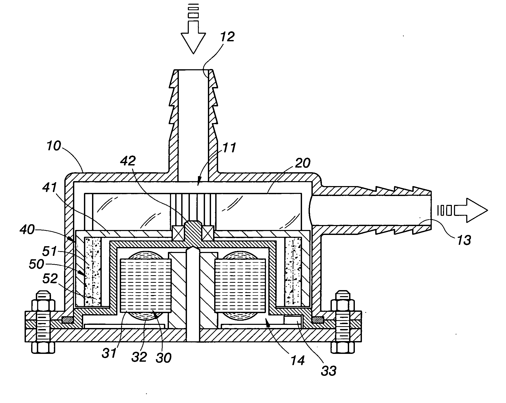
[0023] The outer rotor of the embodiment is placed in the water sucking area for contacting with fluid, by virtue that the annular ferrite magnet is divided into a magnetic conductive outer layer which is not magnetic and a magnetic inner layer, the magnet needs not to have therearound magnetic conductive
metal for forming magnetic loops; i.e., the rotating disk does not need to be made of metallic magnetic conductive material (iron), it can thereby integrally injection molded together with the wheel blade of plastic, this not only can lower the cost of assembling, but also will have no problems of rendering easy oxidation of the metallic magnetic conductive material to result rusting and
corrosion. And the annular ferrite magnet with grain alignment on its inner periphery has the superior features in the wider range of temperature,
humidity durability and alkali resistance; the embodiment can have a broader range of application.
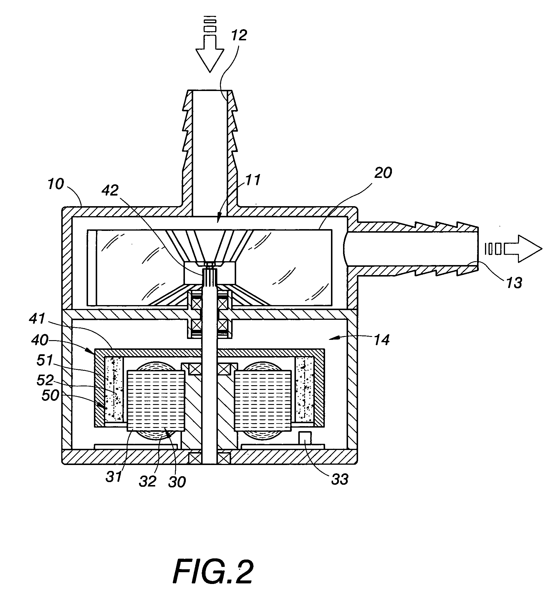
[0025] The principle of this second embodiment is same as that of the first embodiment in using the magnetic coupling mode for transmitting, the difference of it from the first embodiment is: the rotating disk of the outer rotor and the annular ferrite magnet with grain alignment on its inner periphery do not contact with the fluid, and the annular ferrite magnet with grain alignment on its inner periphery is not isolated from the stator, so that the effect of magnetic coupling is better.

