
Building exhaust and air conditioner condensate (and/or other water source) evaporative refrigerant subcool/precool system and method therefor

a technology of building exhaust and air conditioner condensate, which is applied in the direction of ventilation systems, heating types, domestic cooling apparatus, etc., can solve the problems of low efficiency deviating from the ideal cycle of actual refrigeration, and high cost of subcooling and/or precooling and/or postheating, etc. , to achieve the effect of increasing the refrigeration effect, reducing power consumption, and increasing the pumping efficiency

Inactive Publication Date: 2005-02-22
OLIVE TREE PATENTS 1
View PDF30 Cites 29 Cited by
  • Summary
  • Abstract
  • Description
  • Claims
  • Application Information

AI Technical Summary

Benefits of technology

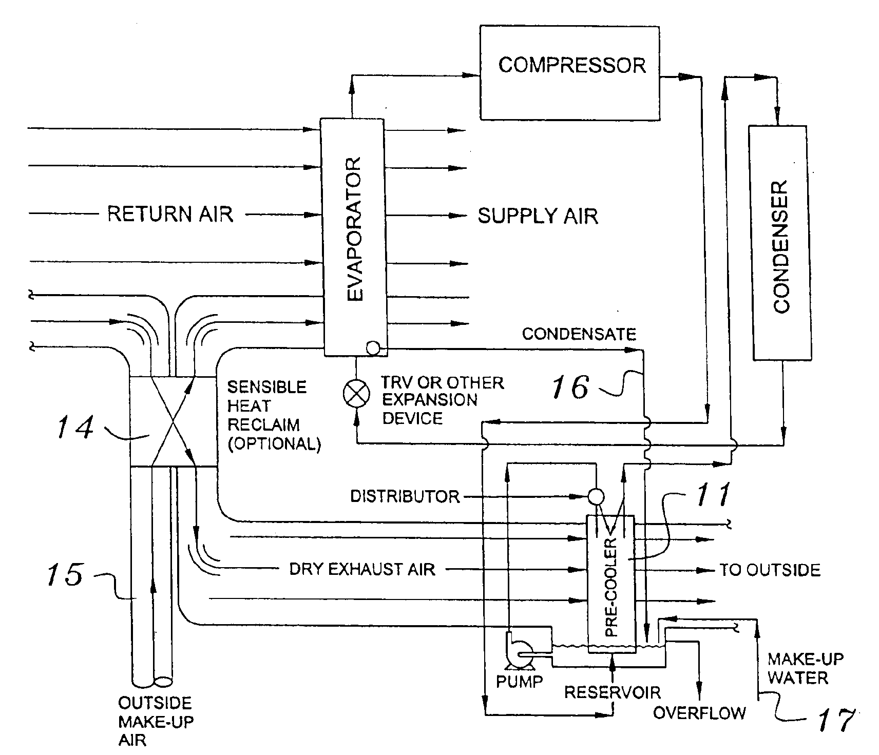
"The present invention is about two apparatuses that improve the performance of air conditioning, refrigeration, or heat pump systems. The first apparatus uses a subcool heat exchanger to increase the refrigerant's cooling effect by using cold, dry air from the building's air supply or outdoor air. This allows for increased refrigeration or heating, depending on the system's needs. The second apparatus uses a precool heat exchanger to cool the hot gas refrigerant before it reaches the condenser. This reduces power consumption, improves pumping efficiency, and increases the performance of the primary condensers. The second apparatus can also be used in a heat pump operating in the heating mode to allow for conductive heating of the refrigerant after it passes through the primary evaporator. Overall, these apparatuses improve the efficiency and performance of air conditioning, refrigeration, or heat pump systems."

Problems solved by technology

However, the actual refrigeration cycle may deviate from the ideal cycle primarily because of pressure drops associated with fluid flow and heat transfer to or from the surroundings.
However, these known methods and devices have drawbacks.
The drawbacks include the high cost of accomplishing the subcooling and / or precooling and / or postheating, and / or the ineffectiveness or degrading effectiveness of the subcooling and / or precooling and / or posting method and / or device.

Method used


Image

  • Building exhaust and air conditioner condensate (and/or other water source) evaporative refrigerant subcool/precool system and method therefor
  • Building exhaust and air conditioner condensate (and/or other water source) evaporative refrigerant subcool/precool system and method therefor
  • Building exhaust and air conditioner condensate (and/or other water source) evaporative refrigerant subcool/precool system and method therefor

Examples


Embodiment Construction

that follows is offered so that the present contribution to the art can be more fully appreciated. Additional features of the invention will be described hereinafter. These form the subject of the claims of the invention. It should be appreciated by those skilled in the art that the conception and the disclosed specific embodiment may be readily utilized as a basis for modifying or designing other structures for carrying out the same purposes of the present invention. It should also be realized by those skilled in the art that such equivalent constructions do not depart from the spirit and scope of the invention as set forth in the appended claims.

BRIEF DESCRIPTION OF THE DRAWINGS

For a more succinct understanding of the nature and objects of the present invention, reference should be directed to the following detailed description taken in connection with the accompanying drawings in which:

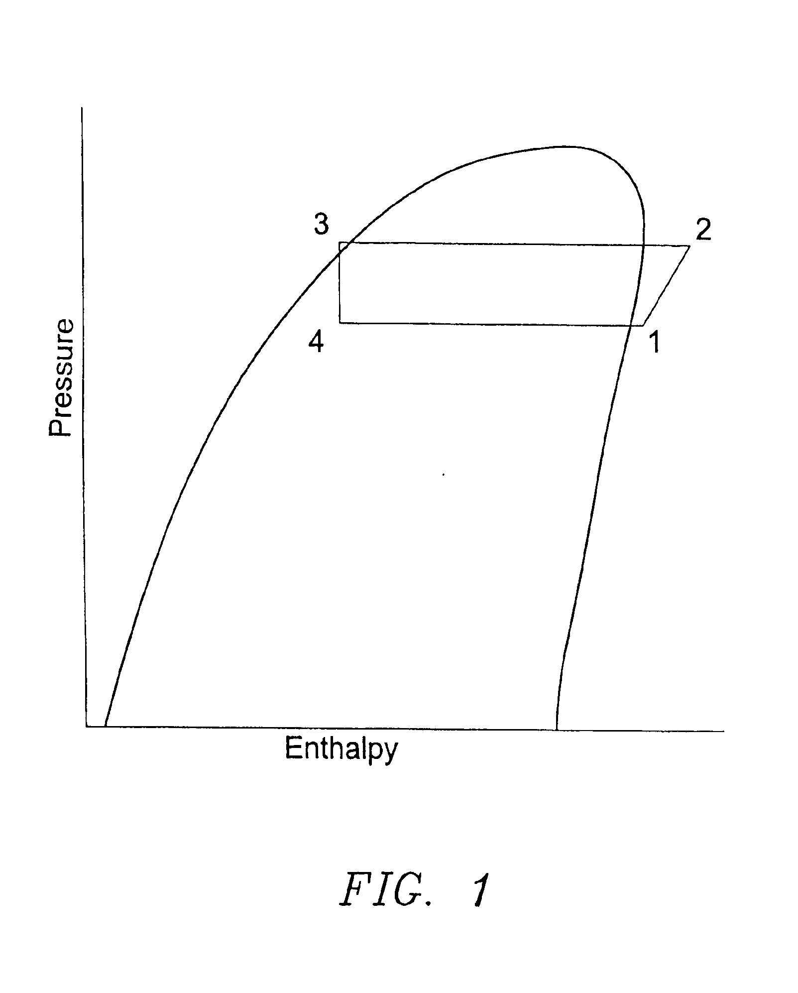
FIG. 1 is a representation of the refrigeration process on a pressure enthalpy diagram.

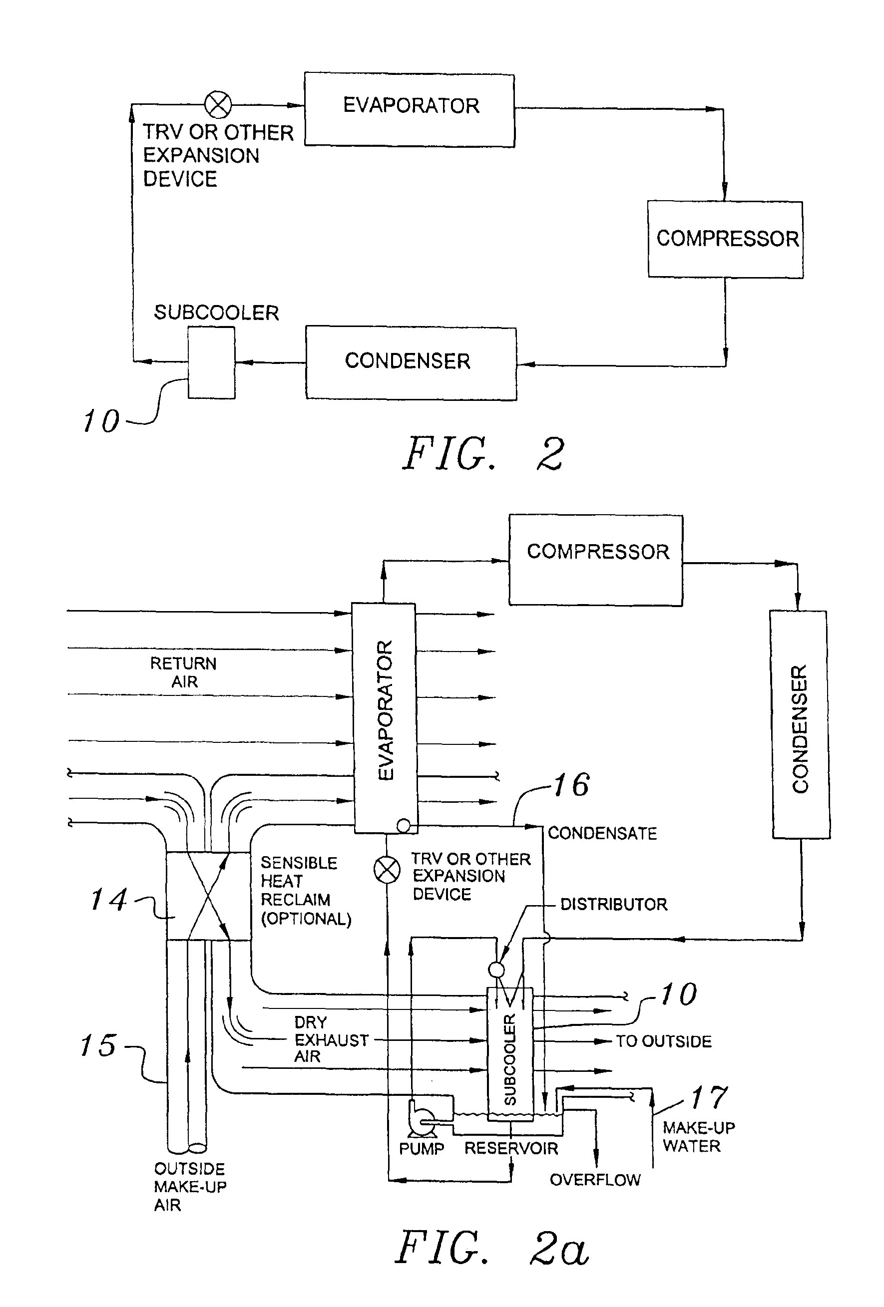
FIG. 2 i...


PUM


Abstract

A system for providing liquid refrigerant subcooling, by means of evaporative cooling utilizing the condensate water of said air conditioner, refrigeration / heat pump system and / or some other water supply to wet the surface of the subcool heat exchanger and pass the dry exhaust air across the wetted surface of the subcool heat exchanger. A system for providing hot gas discharge refrigerant precooling into the primary condenser of an air conditioner, refrigation or heat pump system by evaporative cooling utilizing the condensate water of said system and / or other water supply to wet the surface of the precool heat exchanger and then passing the cold, dry exhaust air across the wetted surface of the precool heat exchanger. A combination subcooler / precooler system where the cold dry building exhaust air is used to evaporatively subcool the liquid refrigerant in the water wetted (or dry) subcooler and then used to conductively cool the hot gas refrigerant.

Description

BACKGROUND OF THE INVENTION1. Field of the InventionThe present invention relates to a subcool and / or precool system for the liquid refrigerant and / or hot gas discharge refrigerant of an air conditioning, refrigeration or heat pump system (cooling mode) that utilizes either the exhaust air required for clean air operation of a building's conditioned air supply only, or the exhaust air and the condensate discharge from said air conditioning, refrigeration or heat pump system (or other water source), or outside air and said condensate (or other water source) to accomplish said subcooling and / or precooling for purposes of increasing the capacity and efficiency of said air conditioning, refrigeration or heat pump system.The present invention further relates to a system for ducting the building exhaust air or outdoor air to said subcool and / or precool system. Said building exhaust air to be used after a preliminary sensible heat exchange with the required incoming make up air if possible...

Claims


Application Information

Patent Timeline
Patent Type & Authority Patents(United States)
IPC IPC(8): F24F12/00F25B40/00F24F1/00F24F1/0071
CPCF24F12/006F25B40/00F24F2001/0092Y02B30/563F25D2321/147Y02B30/545F24F1/0007Y02B30/56F24F1/0071Y02B30/54
Inventor HEBERT, THOMAS H.
Owner OLIVE TREE PATENTS 1
Learn More