Motorcycle wheel stand for parking and transport

a technology for motorcycling and wheel stands, applied in the field of motorcycling stands, can solve the problems of not being able to support the motorcycle in the proper way, not being able to transport modern motorcycles in traditional ways, and being inconvenient to carry, etc., and achieve the effect of saving space and reducing the number of vehicles

Active Publication Date: 2006-12-19
WHEEL DOCK
View PDF37 Cites 39 Cited by
  • Summary
  • Abstract
  • Description
  • Claims
  • Application Information

AI Technical Summary

Problems solved by technology

Even when the center stand is included on a motorcycle, it is not adequate support for transporting the motorcycle.
The strapping down of the motorcycle's front end requires compressing the suspension components, which is not recommended for most modern motorcycles.
These factors make transporting modern motorcycles in traditional ways both impractical and inappropriate.
Placing the motorcycle on its center stand doesn't help conserve space because the rider must first apply the side stand, leave room to dismount, and then pull the bike up on its center stand.
However, there are three major problems shared more or less by all the various stands using the weight-overcenter principle.
1) It is hard to push heavy modern touring-type motorcycles into these stands because these motorcycles must be pushed up and over the elevated pivot point.
2) For the same reasons and especially for riders with shorter legs, it is hard to pull the same heavy motorcycles out of these stands.
3) These stands are difficult for a rider to see when sitting on a motorcycle with a full fairing.
Therefore, hitting the entry shoe with the front wheel becomes a difficult task.
Pushing a bike from the side is very hazardous because a modern touring motorcycle can weigh well in excess of 400 kg.
A lean of just a few degrees off center, especially when the motorcycle leans away from the operator, will result in a very expensive incident.

Method used


Image

  • Motorcycle wheel stand for parking and transport
  • Motorcycle wheel stand for parking and transport
  • Motorcycle wheel stand for parking and transport

Examples


Embodiment Construction

. 1 AND FIG. 2—PREFERRED EMBODIMENT

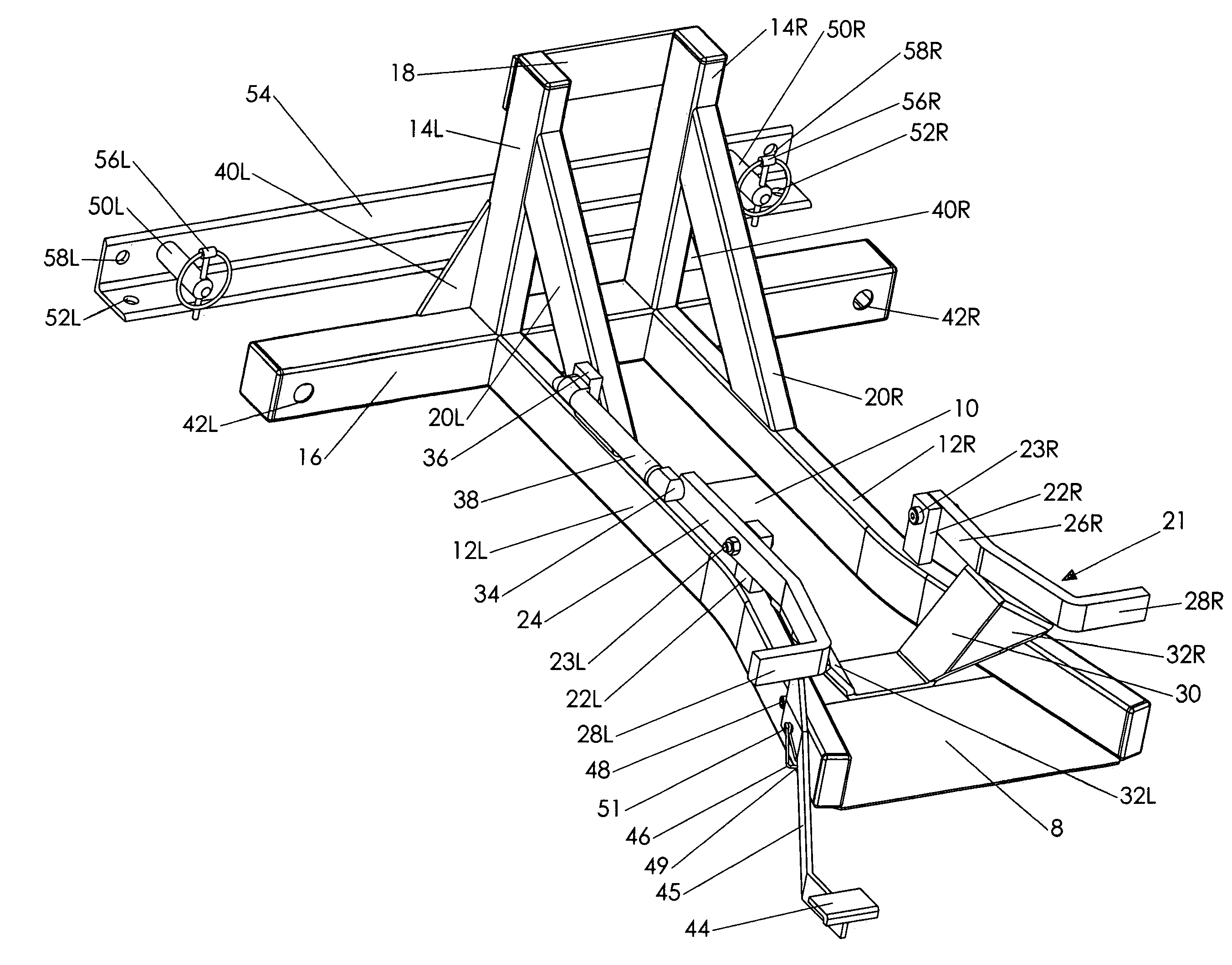
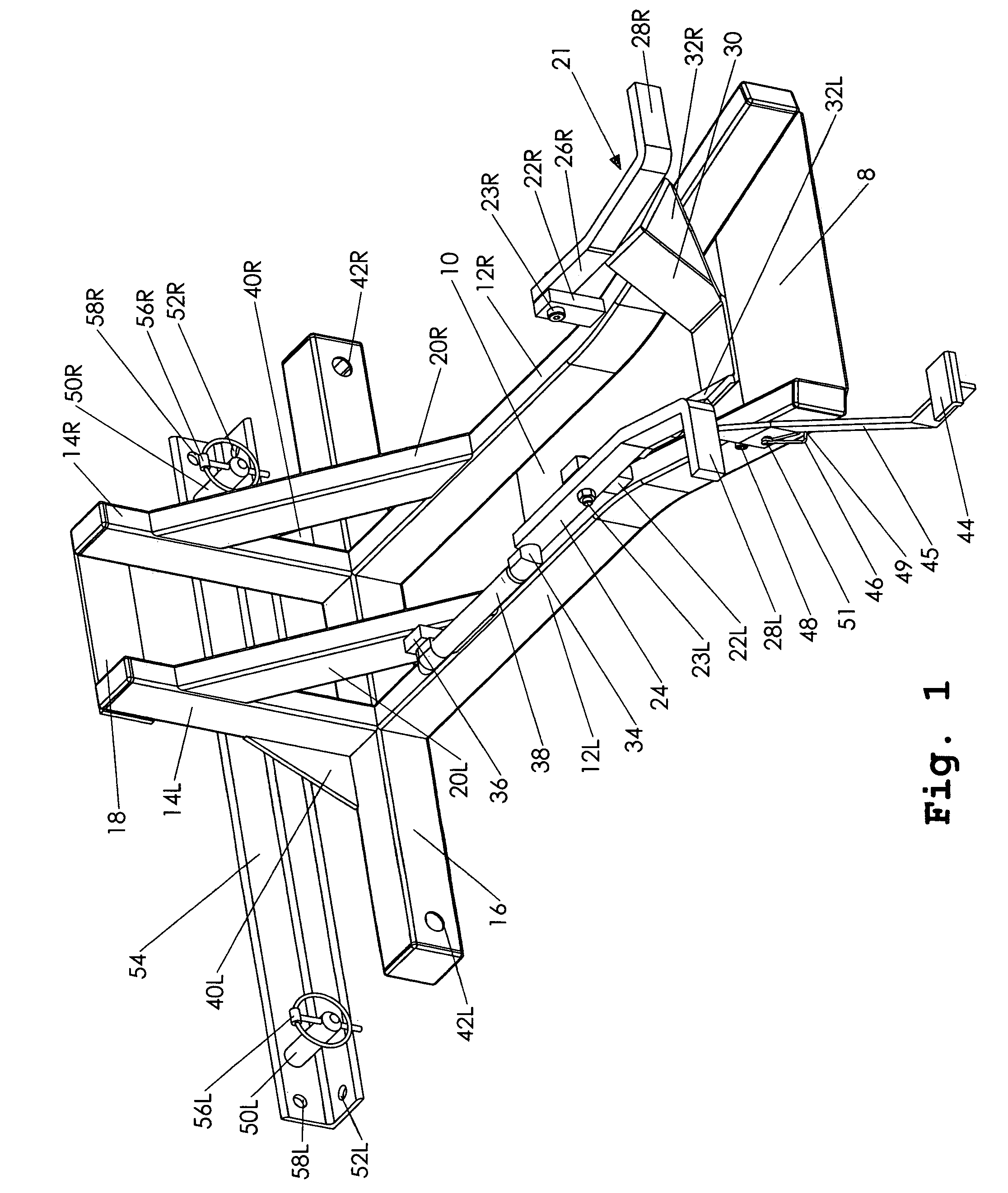
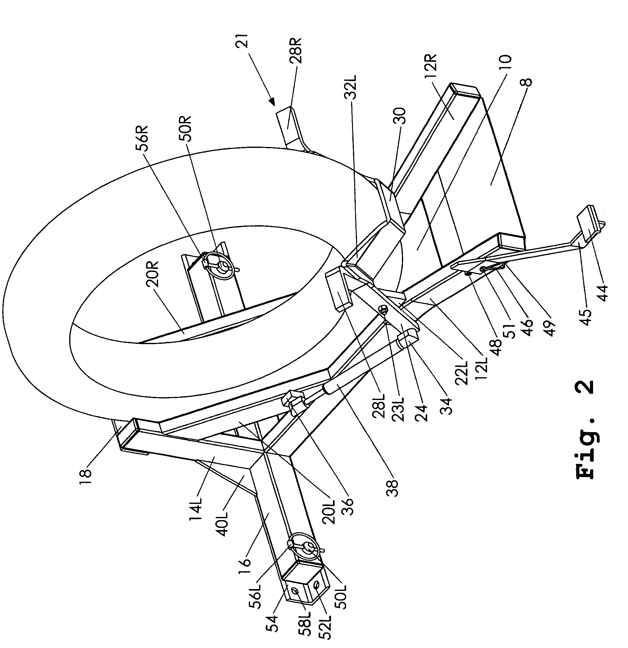
[0035]A preferred embodiment of the present invention is illustrated in FIG. 1 (open position) and FIG. 2 (closed position with wheel shown). Both FIG. 1 and FIG. 2 are shown in perspective view. In addition, FIG. 1 shows a trailer mounting bar 54 detached from a perpendicular stabilizing tube 16 for clarity. FIG. 2 shows bar 54 attached to tube 16.

[0036]The motorcycle stand of the present invention is made up of steel parts attached together by welding, unless otherwise stated. The parts illustrated in FIG. 1 consist of a pair of entry rails 12L and 12R, which are flared away from each other at one end. Rails 12 are bent so as to become parallel and then terminate against tube 16. An entry floor 8 and a central floor 10 are attached to the underside of rails 12L-R. A pair of vertical supports 14L and 14R is attached to tube 16. A pair of braces 20L and 20R is attached to supports 14L-R and rails 12L-R for strength. A stop plate 18 is attached to s...


PUM


Abstract

An improved motorcycle wheel stand having a set of guide rails (12), a set of vertical supports (14), a positive stop (18), and a perpendicular stabilizing tube (16). The wheel is clamped by pressure supplied by an air spring (38) acting upon a pivoting lever (24) attached to a rotating shoe assembly (21) which rotates up and forward against the rear of the wheel, thus pushing the motorcycle into the stand. Removal of the motorcycle is accomplished by the pressing and cocking of assembly (21) by foot and rolling the motorcycle backwards. Assembly (21) is held down by virtue of the center line of spring (38) being out of line relative to spring mounting points (36) and (34) and the pivot point of lever (24).

Description

CROSS-REFERENCE TO RELATED APPLICATIONS[0001]Not ApplicableFEDERALLY SPONSORED RESEARCH[0002]Not ApplicableSEQUENCE LISTING OR PROGRAM[0003]Not ApplicableBACKGROUND OF THE INVENTION[0004]1. Field of Invention[0005]The present invention relates to motorcycle stands, specifically to stands used to secure the front wheel of motorcycles for parking or transport.[0006]2. Discussion of Prior Art[0007]It is often desirable to park a motorcycle in a vertical position as opposed to leaning it over on its side stand. A few of the reasons for parking a motorcycle in a vertical position follow:[0008]1) For safely transporting the motorcycle in a truck or on a trailer[0009]2) For conserving space as in a garage or on a showroom floor[0010]3) For parking racing motorcycles or track bikes where stands mounted to the machines are prohibited[0011]4) For working on the motorcycle or for cleaning where the left side would be hard to access on a side stand[0012]Years ago most motorcycles came equipped ...

Claims


Application Information

Patent Timeline
Patent Type & Authority Patents(United States)
IPC IPC(8): A47F7/00
CPCB62H3/08
Inventor LYONS, CHARLES MICHAELBRAKHAGE, RODNEY DEAN
Owner WHEEL DOCK
Why Eureka
Try Eureka