Clamp terminal for connecting electrical conductors

a technology of electrical conductors and clamp terminals, which is applied in the direction of one-pole connection, contact member penetration/cutting of insulation/cable strands, electrical apparatus, etc., can solve the problem of consuming a lot of cu materials, and achieve the effect of reducing structural siz

Inactive Publication Date: 2006-12-19
WAGO VERW GMBH
View PDF15 Cites 35 Cited by
  • Summary
  • Abstract
  • Description
  • Claims
  • Application Information

AI Technical Summary

Benefits of technology

[0010]It is an important advantage that in the clamp terminal according to the invention, the minimum structural width of the spring steel sheet for the support plate and the minimum structural width of the spring steel sheet for the leaf spring are not added in the direction of the conductive core rod, so that multiple clamp terminals that are reduced in structural size can be produced with a plurality of single clamp terminals.
[0012]The shared loading of the two pieces of spring steel sheet need not be equal. Any distribution of the spring excursion on one or the other piece of spring steel sheet may be of advantage when the clamping site is opened, as long as opening is always achieved in this way; the length of the leaf spring tabs can be designed so that they are short, which also can be utilized for a reduction in structural size.

Problems solved by technology

Relatively expensive Cu material is used only in an amount that is necessary for purposes of current conduction.

Method used


Image

  • Clamp terminal for connecting electrical conductors
  • Clamp terminal for connecting electrical conductors
  • Clamp terminal for connecting electrical conductors

Examples


Embodiment Construction

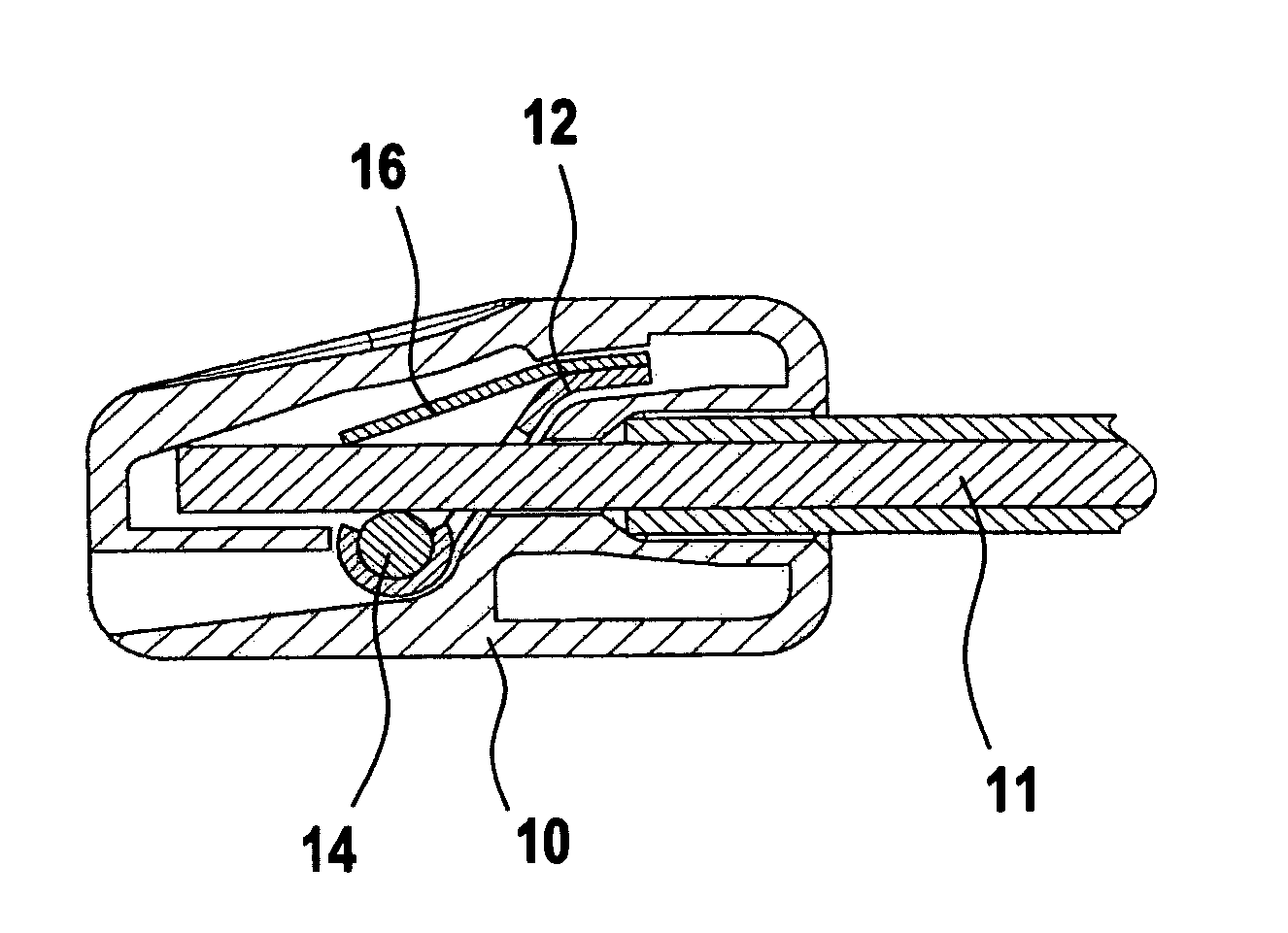
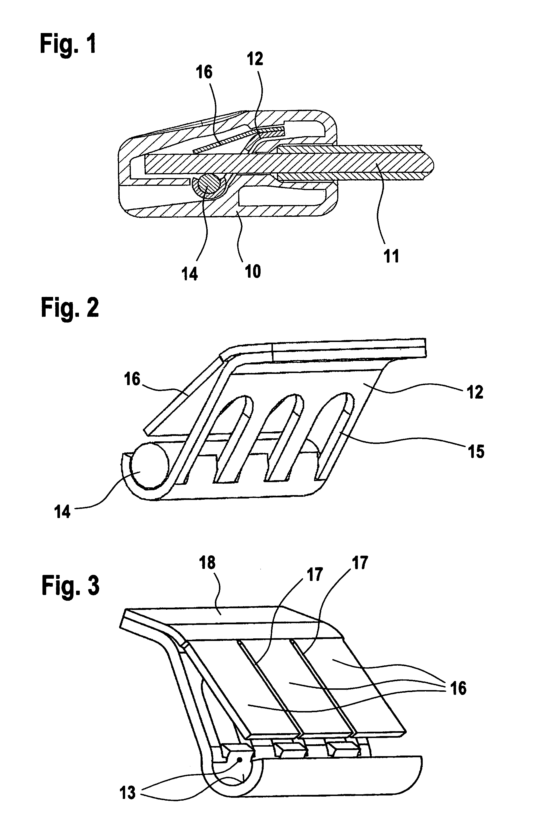
[0018]FIG. 1 shows the insulation housing 10 of a so-called box clamp terminal, i.e., connection clamp terminals for connecting several electrical conductors 11, which will be electrically connected to one another, e.g., in a distribution box of a building installation.

[0019]FIGS. 2 and 3 show the contact insert of the box clamp terminal according to FIG. 1, comprising a piece of spring steel sheet 12 for the support plate, this sheet possessing a shaped uptake locking profile 13 in the lower region of the drawing (see FIG. 3), in which a round conductive core rod 14 is locked (see FIG. 2). The spring steel sheet 12 for the support plate possesses a conductor opening 15 for each clamping site, and an electrical conductor 111 which is to be connected is inserted through this opening (see FIG. 1), in order to then be electrically and mechanically clamped in the allotted clamping site between a leaf spring tab 16 and the conductive core rod 14.

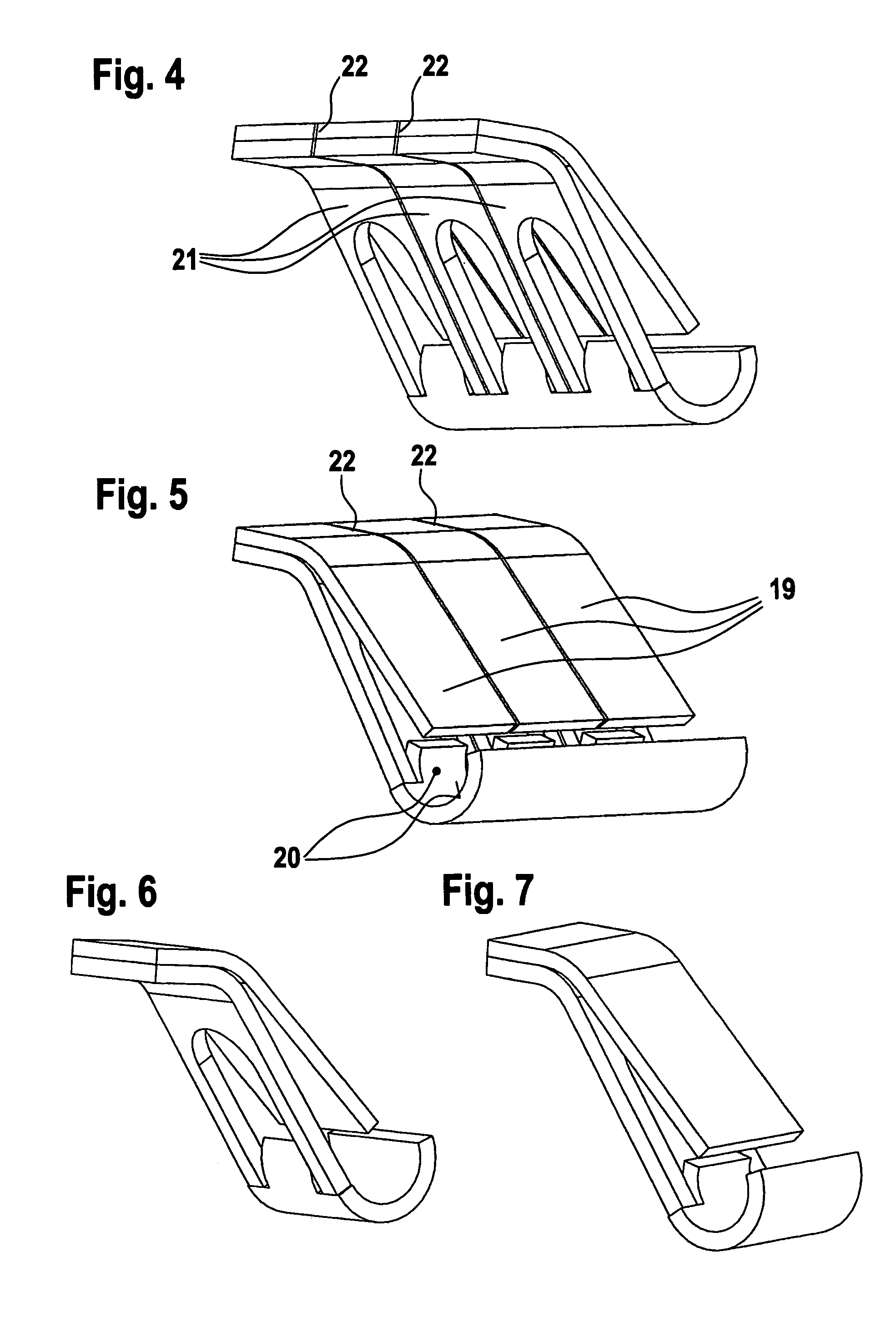
[0020]In the example of embodiment accordi...


PUM


Abstract

A clamp terminal for connecting electrical conductors, which can be produced in a manner that reduces the structural size and optimizes costs. For this purpose, the clamp terminal includes two pieces of spring steel sheet, i.e., a spring steel sheet for the support plate and a spring steel sheet for the leaf spring, which are spot-welded in their head regions. The spring steel sheet for the support plate possesses in its foot region an uptake locking profile, in which, preferably, a round conductive core rod is engaged. Leaf spring tabs are formed from the spring steel sheet for the leaf spring, whose tab ends, together with the conductive core rod, form clamping sites for connecting the electrical conductors.

Description

TECHNICAL FIELD[0001]The invention concerns a single clamp terminal as well as multiple clamp terminals formed therefrom for connecting one or more electrical conductors.BACKGROUND DISCUSSION[0002]Since 1973 (see DE 2,317,040 C3) and since 1995 (see DE 295 12 567 U1), clamp terminals of this type have been known, which use a rigid, solid support plate comprised of an electrically well-conducting material (e.g, made of a Cu material), which provides a large surface over all terminal sites of a multiple clamp terminal. On this support plate, which provides the electrically conducting connection between the individual clamping sites as well as represents the bearing element for all single clamp terminals joined together into a multiple clamp terminal, a leaf spring tab of spring steel sheet metal is fastened for each single clamp terminal and, in fact, for the most part, in such a way that all leaf spring tabs have a common head piece of spring steel sheet, which is fastened to the sup...

Claims


Application Information

Patent Timeline
Patent Type & Authority Patents(United States)
IPC IPC(8): H01R4/24H01R4/48H01R11/20
CPCH01R4/4818H01R9/24H01R11/09H01R2101/00H01R4/48185
Inventor TRUMPER, THOMAS
Owner WAGO VERW GMBH
Why Eureka
Try Eureka