
System and method for estimating separation distance between impulse radios using impulse signal amplitude

a technology of impulse radio and amplitude, applied in the field of radio signals, can solve the problems of -to-one (30:1) distance measurement errors, narrow band, and system disadvantageous to complex transceiver circuitry and/or time-synchronization techniques, and achieve the effect of resisting multipath fading effects, improving separation distance estimates, and improving performan

Inactive Publication Date: 2006-12-19
HUMATICS CORP
View PDF40 Cites 84 Cited by
  • Summary
  • Abstract
  • Description
  • Claims
  • Application Information

AI Technical Summary

Benefits of technology

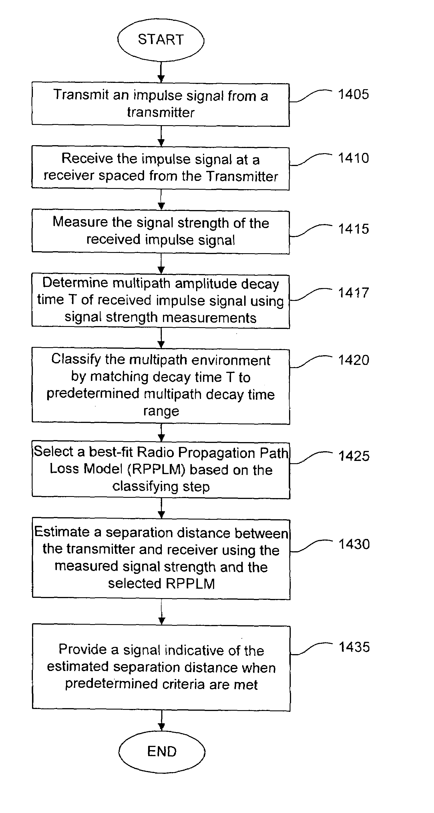
[0008]The present invention is directed to a multipath resistant, impulse radio system for estimating a separation distance between an impulse radio transmitter and an impulse radio receiver. The system includes an impulse transmitter for transmitting an impulse signal having one or more of an ultra-wideband or medium wideband frequency characteristic. The ultra-wideband and medium wideband impulse signal advantageously resists multipath fading effects. An impulse receiver spaced from the transmitter receives the transmitted, multipath resistant impulse signal. The receiver includes a signal evaluator configured to measure a signal strength of the received impulse signal. An estimator, coupled to the evaluator, estimates the separation distance based on the measured signal strength. The present invention improves the accuracy of the separation distance estimate over known systems by utilizing multipath resistance afforded by the impulse radio signal. Accordingly, the separation distance estimation accuracy in the present invention is relatively immune to multipath effects compared to narrow band amplitude methods. As a result, the present invention offers performance improvements over narrow band amplitude based methods and a simpler solution compared to timing based methods.
[0009]In one embodiment of the present invention, the receiver receives a plurality of impulse signals including impulse signals arising from multipath effects. The receiver classifies a signal propagational / multipath environment using the received impulse signals, and then selects a radio propagation path loss model corresponding to a classified multipath environment. The estimator translates the measured signal strength to a separation distance based on the selected radio propagation path loss model. In doing so, the receiver further improves the accuracy of the separation distance estimate because the estimate takes into account information regarding the propagation environment, which can be deduced from patterns in received multipath impulse signals.

Problems solved by technology

Such a system disadvantageously requires complex transceiver circuitry and / or techniques for time-synchronizing the receiver to the transmitter, and for measuring signal time-of-arrival at the receiver.
Although less complex and generally less expensive than the time-based system, the narrow band, amplitude-based system disadvantageously suffers from multipath fading processes.
This is especially true of mobile urban environments and within edifices where multipath effects may be so extreme as to cause 6 decibels (dB) or more root-means-square signal strength deviations with more than 30 dB or more signal strength nulls at the receiver, resulting in thirty-to-one (30:1) distance measurement errors.
Such large signal strength fluctuations as a function of receiver position lead to inaccurate separation distance estimates and render known amplitude-based systems unusable.
However, such efforts have had only limited success.

Method used


Image

  • System and method for estimating separation distance between impulse radios using impulse signal amplitude
  • System and method for estimating separation distance between impulse radios using impulse signal amplitude
  • System and method for estimating separation distance between impulse radios using impulse signal amplitude

Examples


Embodiment Construction

[0039]

Table of ContentsI.Impulse Radio Basics I.1. Waveforms I.2. Pulse Trains I.3. Coding for Energy Smoothing and Channelization I.4. Modulation I.5. Reception and Demodulation I.6. Interference Resistance I.7. Processing Gain I.8. Capacity I.9. Multipath and PropagationI.10. Distance Measurement Using Time MeasurementsII.Exemplary Transceiver ImplementationII.1. TransmitterII.2. ReceiverIII.Overview of the InventionIV.Impulse Radio TransceiverIV.1. Transceiver OverviewIV.2. Receiver OperationIV.2.a. Signal DetectionIV.2.b. Signal Strength MeasurementV.Determining Separation DistanceV.1. OverviewV.2. Amplitude-Time Multipath Waveform AnalysisV.3. Radio Propagation Path Loss ModelsV.4. Detailed Process for Estimating Separation DistanceVI.Exemplary Transceiver Computer SystemVII.Exemplary Transceiver Comparator SystemVIII.Conclusion

I. Impulse Radio Basics

[0040]This section is directed to technology basics and provides the reader with an introduction to impulse radio concepts, as we...


PUM


Abstract

A method and system are provided for locating an impulse radio. Impulse radio signals are communicated between a first impulse radio and a plurality of second impulse radios. A received signal strength measurement is determined for each of the impulse radio signals. One of a plurality of radio propagation path models is selected and used to estimate a plurality of separation distances between the first impulse radio and the plurality of second impulse radios. The plurality of separation distances is used to determine a location relating to the first impulse radio.

Description

CROSS-REFERENCE TO RELATED APPLICATIONS[0001]This application is a continuation of U.S. Non-Provisional application Ser. No. 09 / 537,263, filed Mar. 29, 2000, entitled “System and Method for Estimating Separation Distance Between Impulse Radios Using Impulse Signal Amplitude” now U.S. Pat. No. 6,700,538 issued Mar. 2, 2004, which is incorporated herein by reference in its entirety. This application is also related to U.S. Non-Provisional application Ser. No. 09 / 045,929, filed Mar. 23, 2008, entitled “System and Method for Person or Object Position Location Utilizing Impulse Radio, ” now U.S. Pat. No. 6,133,876 issued Oct. 17, 2000, and U.S. Non-Provisional application Ser. No. 09 / 332,501, filed Jun. 14, 1999, entitled “System and Method for Impulse Radio Power Control, ” now U.S. Pat. No. 6,539,218 issued Mar. 25, 2003, which are incorporated herein by reference in their entireties.BACKGROUND OF THE INVENTION[0002]1. Field of the Invention[0003]The present invention relates generally...

Claims


Application Information

Patent Timeline
Patent Type & Authority Patents(United States)
IPC IPC(8): G01S3/02G01S11/06
CPCG01S11/06H04B2001/6908
Inventor RICHARDS, JAMES L.
Owner HUMATICS CORP
Learn More