Simple inspection device for wheel alignment
- Summary
- Abstract
- Description
- Claims
- Application Information
AI Technical Summary
Benefits of technology
Problems solved by technology
Method used
Image
Examples
Embodiment Construction
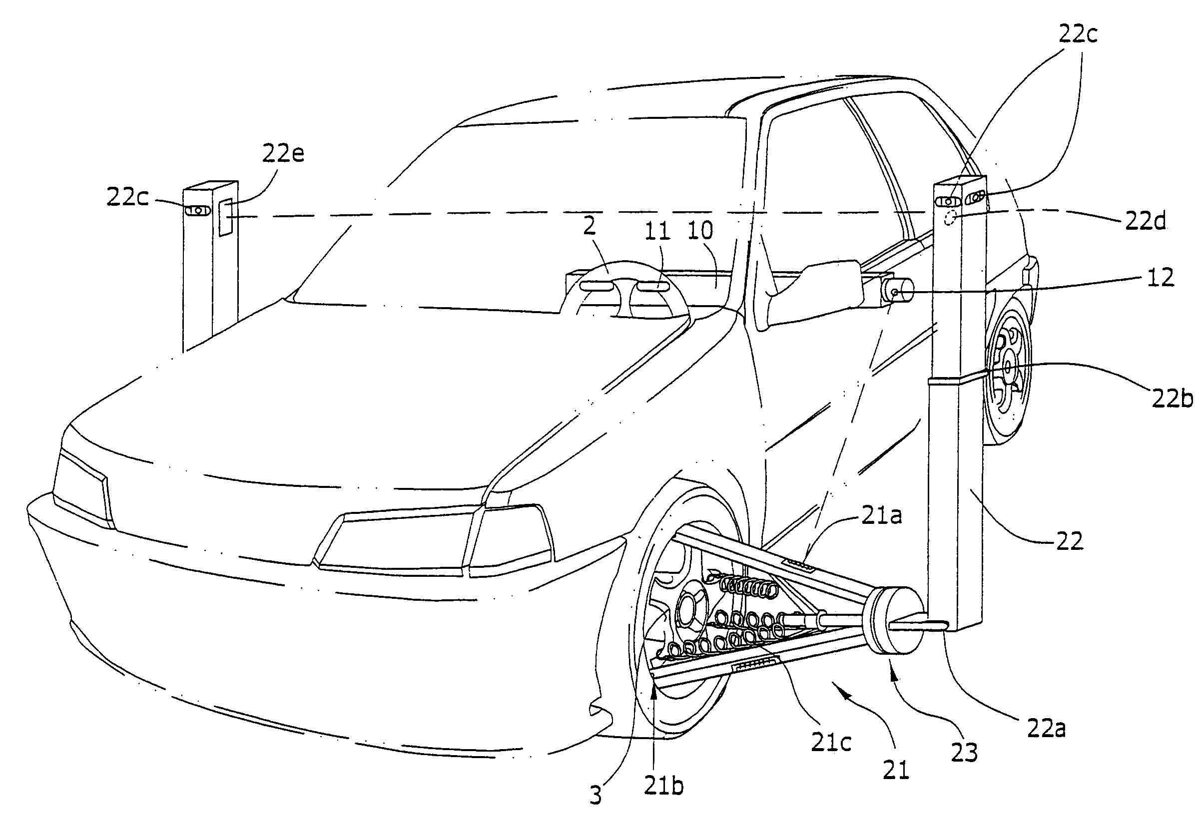
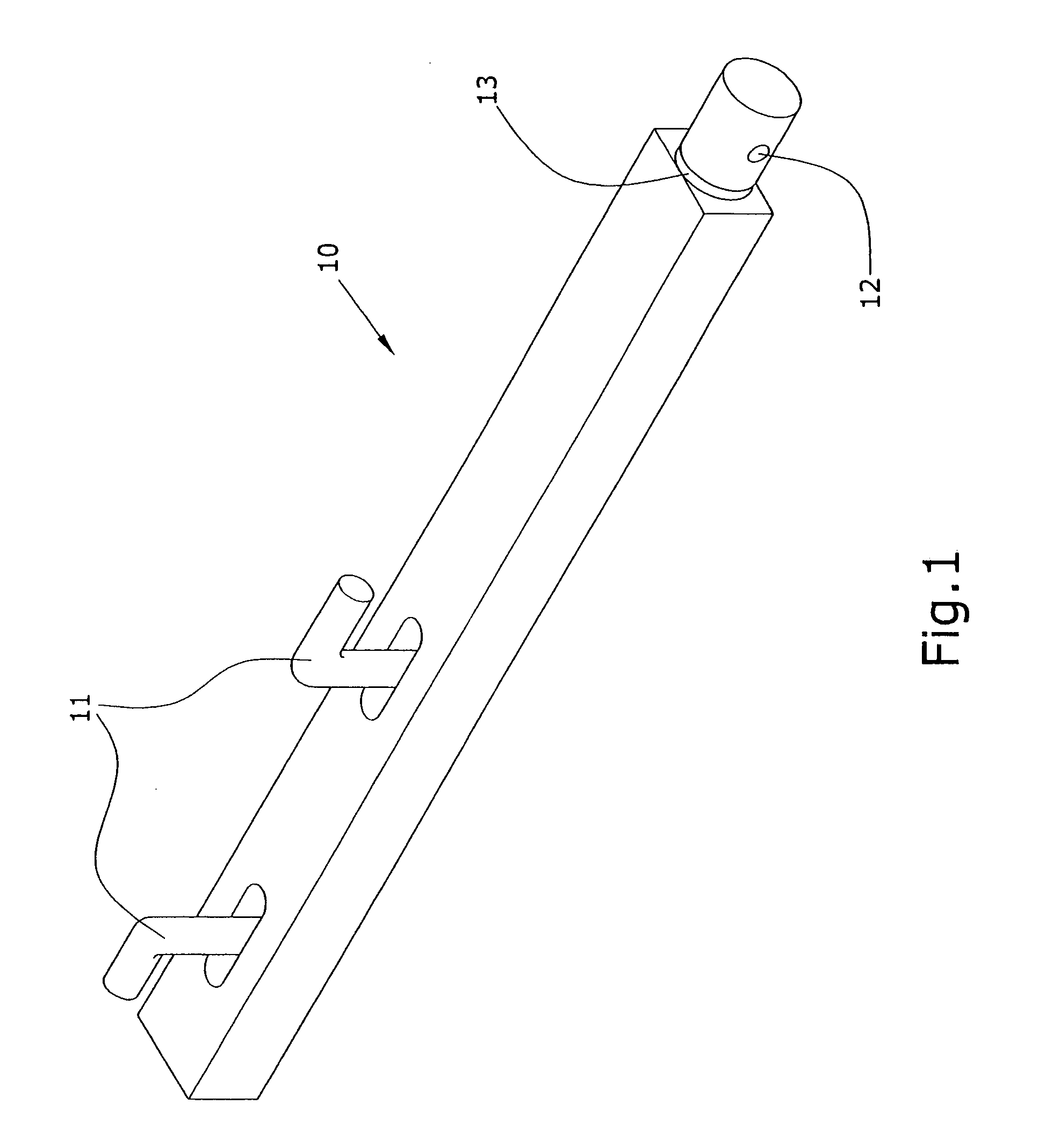
[0014]Referring to FIG. 1, FIG. 2, and FIG. 3, the present invention comprises a level inspecting rod 10 and two alignment inspecting racks 20, wherein a fixing member 11 and a light emitter 12 are located at two ends of the level inspecting rod 10, respectively. The fixing member 11 is used to fix on a steering wheel 2, and the light emitter 12 is located on a rotating member 13. Light can be shining on a scale meter 21a on a bracket 21 by adjusting the rotating member 13.
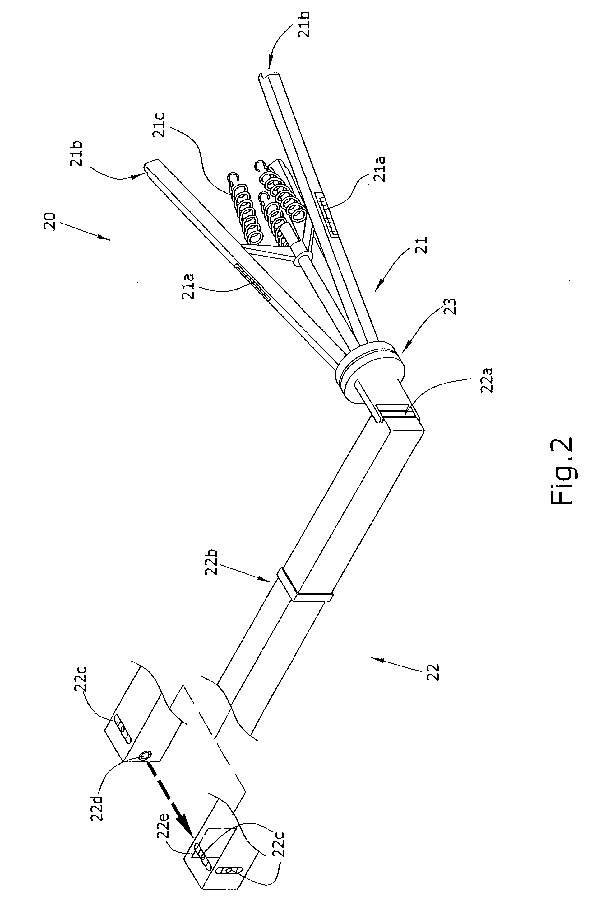
[0015]A three-leg bracket 21 is located at a bottom of the alignment inspecting rack 20, with the scale meter 21a located at a proper position on a surface of the bracket 21. A lean-against member 21b which can be latched on an edge of a frame 3 is located at a bottom of the bracket 21, and a tension member 21c which can be hooked on the frame 3 is located at a central part of the bracket 21. The tension member 21c can be a spring or an elastic rope. A rotating member 23 which is installed at a connection point be...
PUM
 Abstract
Description
Claims
Application Information
 - R&D
- Intellectual Property
- Life Sciences
- Materials
- Tech Scout
- Unparalleled Data Quality
- Higher Quality Content
- 60% Fewer Hallucinations
Browse by: Latest US Patents, China's latest patents, Technical Efficacy Thesaurus, Application Domain, Technology Topic, Popular Technical Reports.
© 2025 PatSnap. All rights reserved.Legal|Privacy policy|Modern Slavery Act Transparency Statement|Sitemap|About US| Contact US: help@patsnap.com


