Al technical title is built by PatSnap Al team. It summarizes the technical point description of the patent document.
a gunstock and modular technology, applied in the field of rifle stock, can solve the problems of lack of uniform cheek welds, affecting the comfort and precise use of weapons, and stock stability, and not describing a truly modular stock
Inactive Publication Date: 2006-12-26
MAGPUL INDUSTRIES
View PDF10 Cites 104 Cited by
Summary
Abstract
Description
Claims
Application Information
AI Technical Summary
This helps you quickly interpret patents by identifying the three key elements:
Problems solved by technology
Method used
Benefits of technology
Problems solved by technology
The lack of uniform cheek weld can interfere with comfortable and precise use of the weapon.
Stock stability can also interfere with precise weapon use.
While the aforementioned inventions accomplish their individual objectives, they do not describe a truly modular stock, namely a stock where the butt portion is designed to be changed at the whim or need of the user.
Method used
Image
Click on the blue label to locate the original text in one second.
Reading with bidirectional positioning of images and text.
Examples
Embodiment Construction
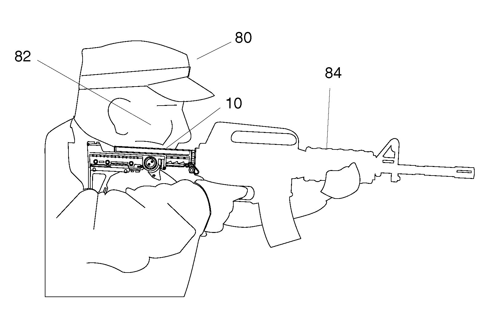
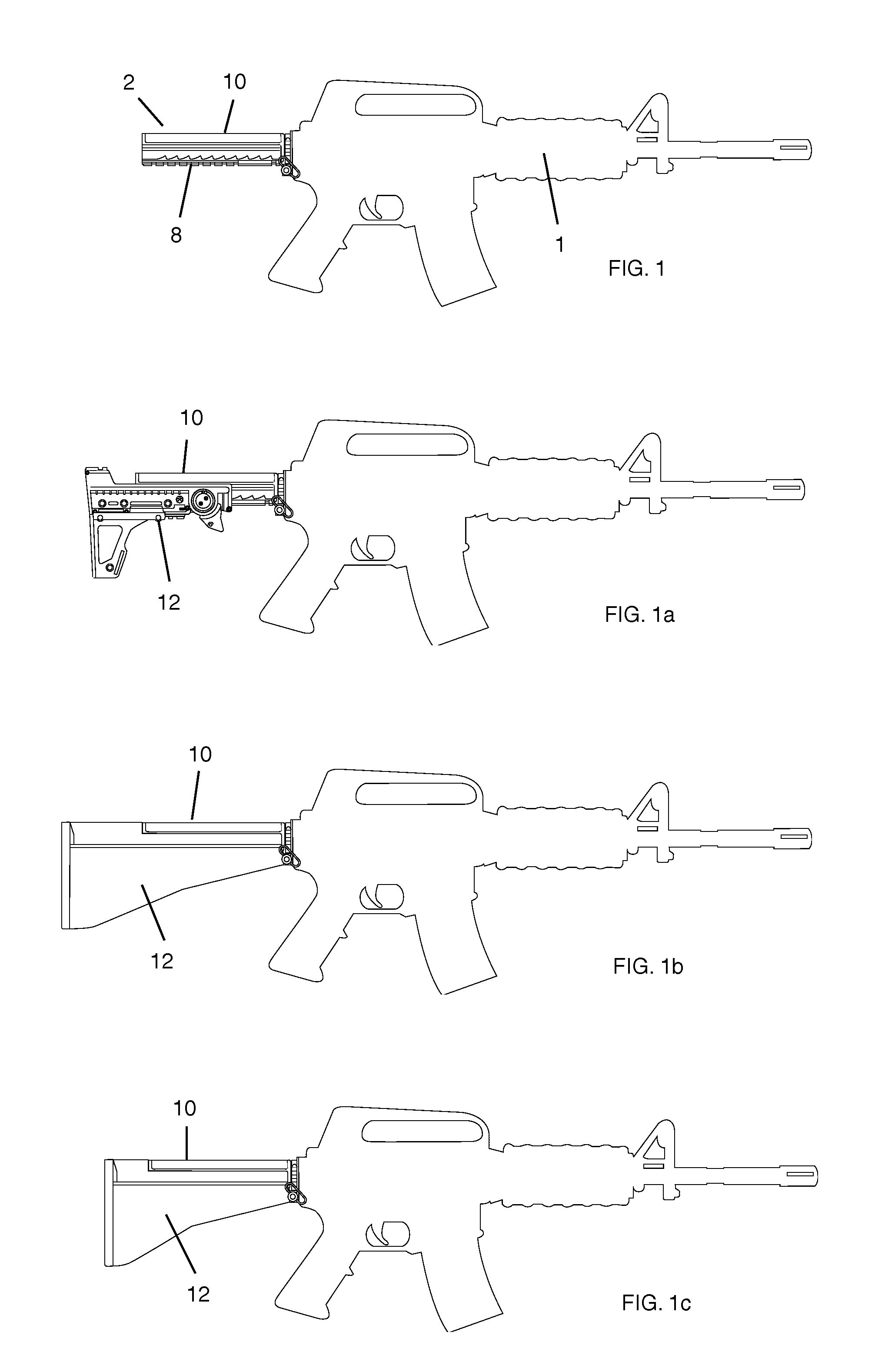
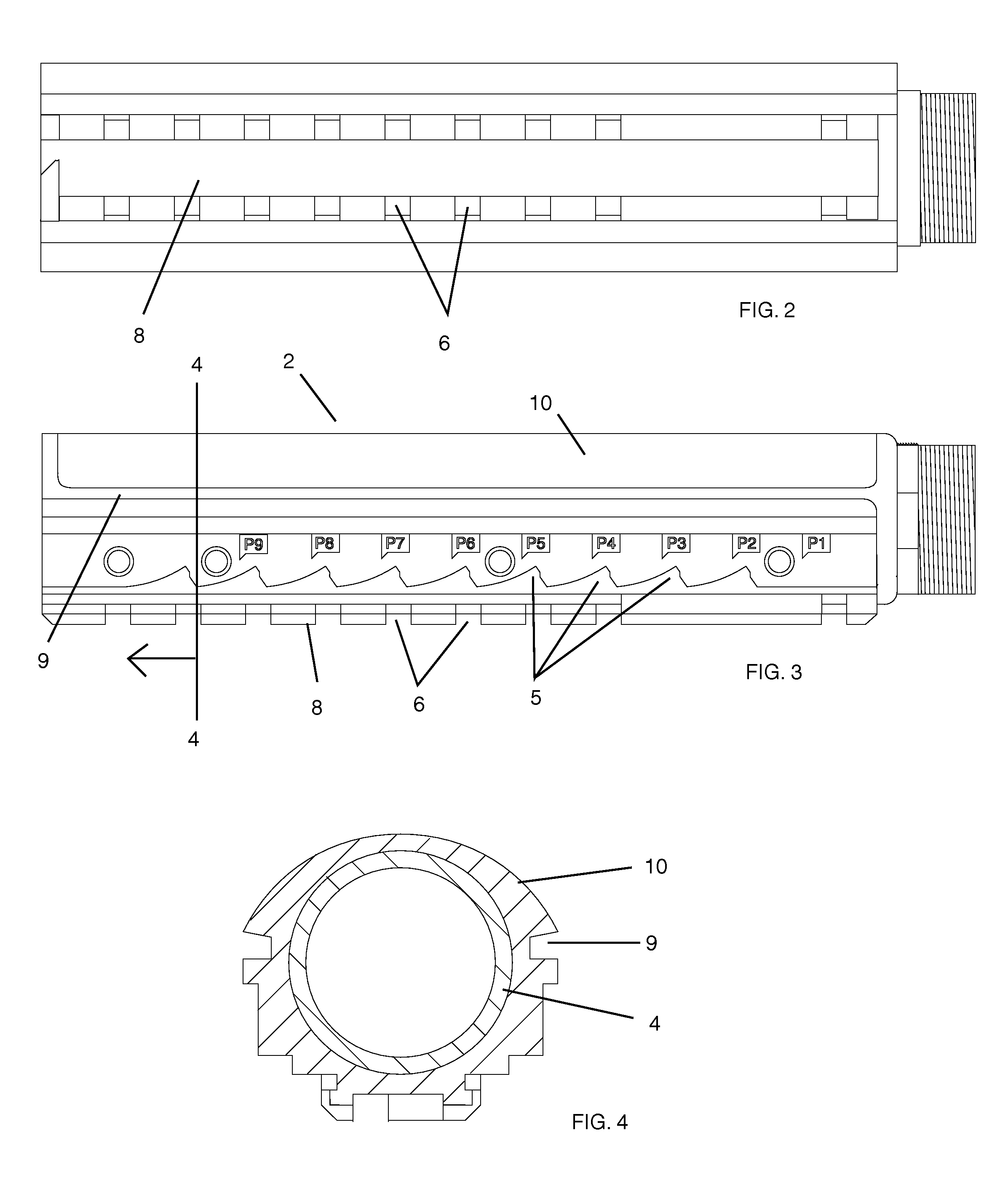
[0030]With reference now to the drawings, the preferred embodiment of the modular gunstock will be explained. With reference to FIGS. 1, 1a, 1b, 1c, the gunstock is composed of a modified buffer tube module 2 and a stock module 12. Buffer tube 2 fits on rifle 1 by replacing the existing buffer tube of the rifle with the buffer tube module 2. In addition, referencing FIGS. 3 and 4, rail track 8, with individual lateral grooves 6 and single transverse groove 7, is disposed towards the ground and cheek mount 10 is disposed upwards and is generally parallel to buffer tube 4. Two longitudinal tracks 9 are disposed slightly underneath cheek plate 10 providing attachment tracks for stock module 12. Ideally, the cheek plate 10 is fused onto the buffer tube 2. However, in alternative embodiments, enough space can be left between buffer tube 4 and cheek plate 10 to allow for unhindered motion of a cylindrical stock module. Tooth interfaces 5 are disposed underneath the longitudinal tracks 9.
[...
PUM
Abstract
The present invention is a modular stock system for rifles. The system replaces the rifle's buffer tube with a modified one containing a mount for a constant cheek weld and a rail track for adjustment. A stock module then mounts on the replacement buffer tube. The stock module is interchangeable depending on the user's needs. Various configurations of the stock module are discussed, including adjustable stocks, fixed stocks, and specialized stocks. The stock module may be made even further modular by the addition of rail system.
Description
CROSS-REFERENCE TO RELATED APPLICATIONS[0001]This application is a continuation application based on earlier filed application Ser. No. 10 / 180,429, filed on Jun. 25, 2002, now U.S. Pat. No. 6,651,371, said Application hereby incorporated herein by reference.FIELD OF INVENTION[0002]The present invention relates to a rifle stock and more particularly related to a modular gunstock that provides a constant surface for a uniform cheek weld and the option of a variable length feature.BACKGROUND OF THE INVENTION[0003]Adjustable gunstocks are known in the prior art. For example, U.S. Pat. No. 4,735,007 to Gal (1988); U.S. Pat. No. 4,327,626 to McQueen (1982); U.S. Pat. No. 3,442,042 to Gilbert (1967); U.S. Pat. No. 3,348,328 to Roy (1966); U.S. Pat. No. 3,267,601 to Roy (1964); 3,137,958 to Lewis, et al. (1962); U.S. Pat. No. 5,827,992 to Harris, et al. (1998) and U.S. Pat. No. 2,900,877 to McClenahan (1956) are all illustrative of the prior art.[0004]The current standard in automatic and s...
Claims
Application Information
Patent Timeline
Application Date:The date an application was filed.
Publication Date:The date a patent or application was officially published.
First Publication Date:The earliest publication date of a patent with the same application number.
Issue Date:Publication date of the patent grant document.
PCT Entry Date:The Entry date of PCT National Phase.
Estimated Expiry Date:The statutory expiry date of a patent right according to the Patent Law, and it is the longest term of protection that the patent right can achieve without the termination of the patent right due to other reasons(Term extension factor has been taken into account ).
Invalid Date:Actual expiry date is based on effective date or publication date of legal transaction data of invalid patent.
Patent Type & Authority Patents(United States)
IPC IPC(8): F41C23/00F41C23/04F41C23/14F41C23/20
CPCF41C23/04F41C23/14F41C23/20
Inventor FITZPATRICK, RICHARD M.HINES, STEPHEN CHARLES