Combination workover and drilling rig

Inactive Publication Date: 2006-12-26
TOM C GIPSON
View PDF7 Cites 41 Cited by
  • Summary
  • Abstract
  • Description
  • Claims
  • Application Information

AI Technical Summary

Benefits of technology

[0009]The invention contemplates an improved workover and drilling rig for solving the problems and disadvantages of the prior approaches discussed above. The present invention provides a combination workover and drilling rig that performs well mainte

Problems solved by technology

While these conventional rigs are readily transportable, easy to rig up and down, and economical, they are limited to use with either one or the other type of tubular.
This combination rig is very top heavy and wind sensitive.
Furthermore, when the mast is stowed, the weight distribution of the rig is overly concentrated on the forward end of the t

Method used


Image

  • Combination workover and drilling rig
  • Combination workover and drilling rig
  • Combination workover and drilling rig

Examples


Embodiment Construction

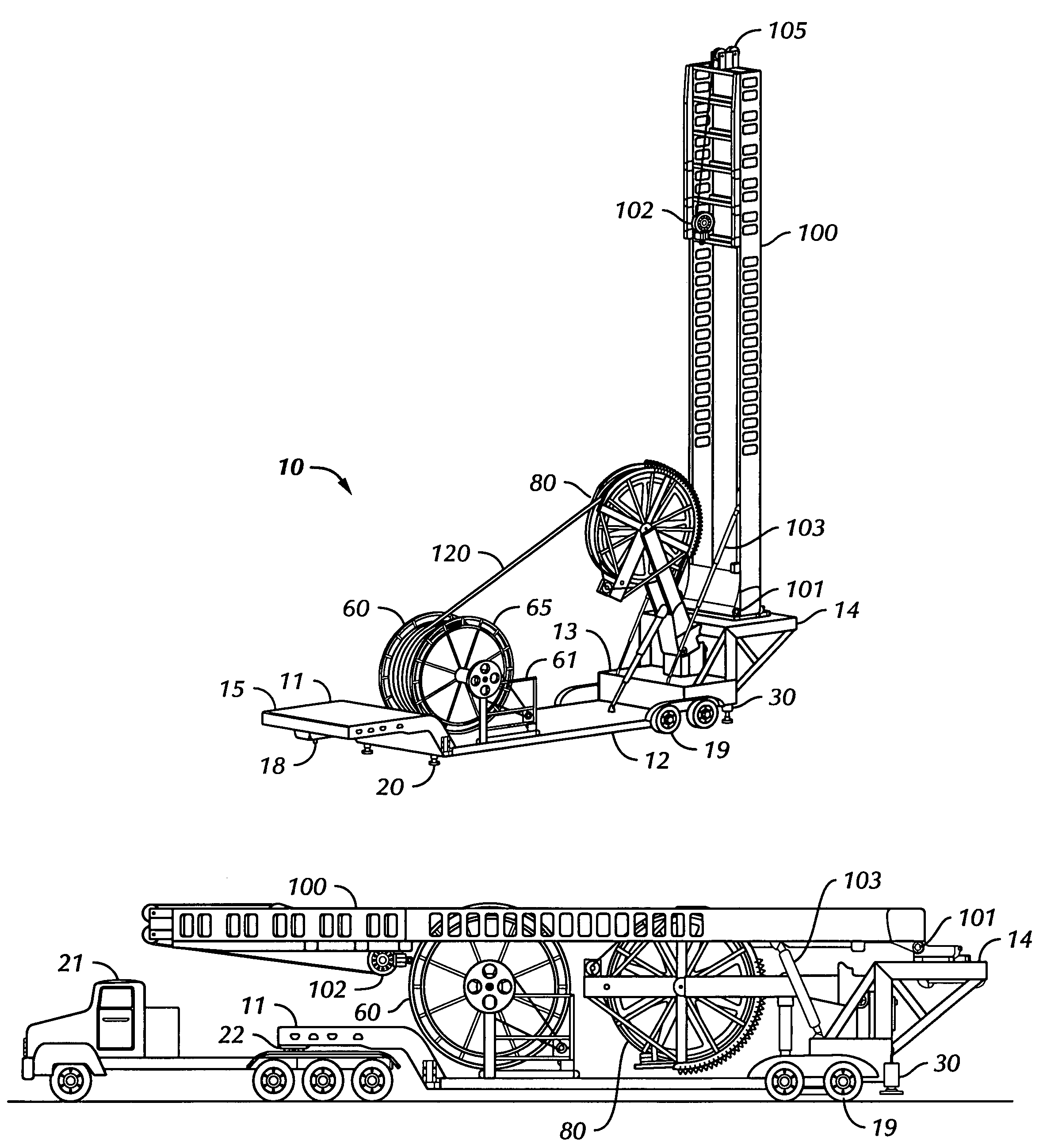
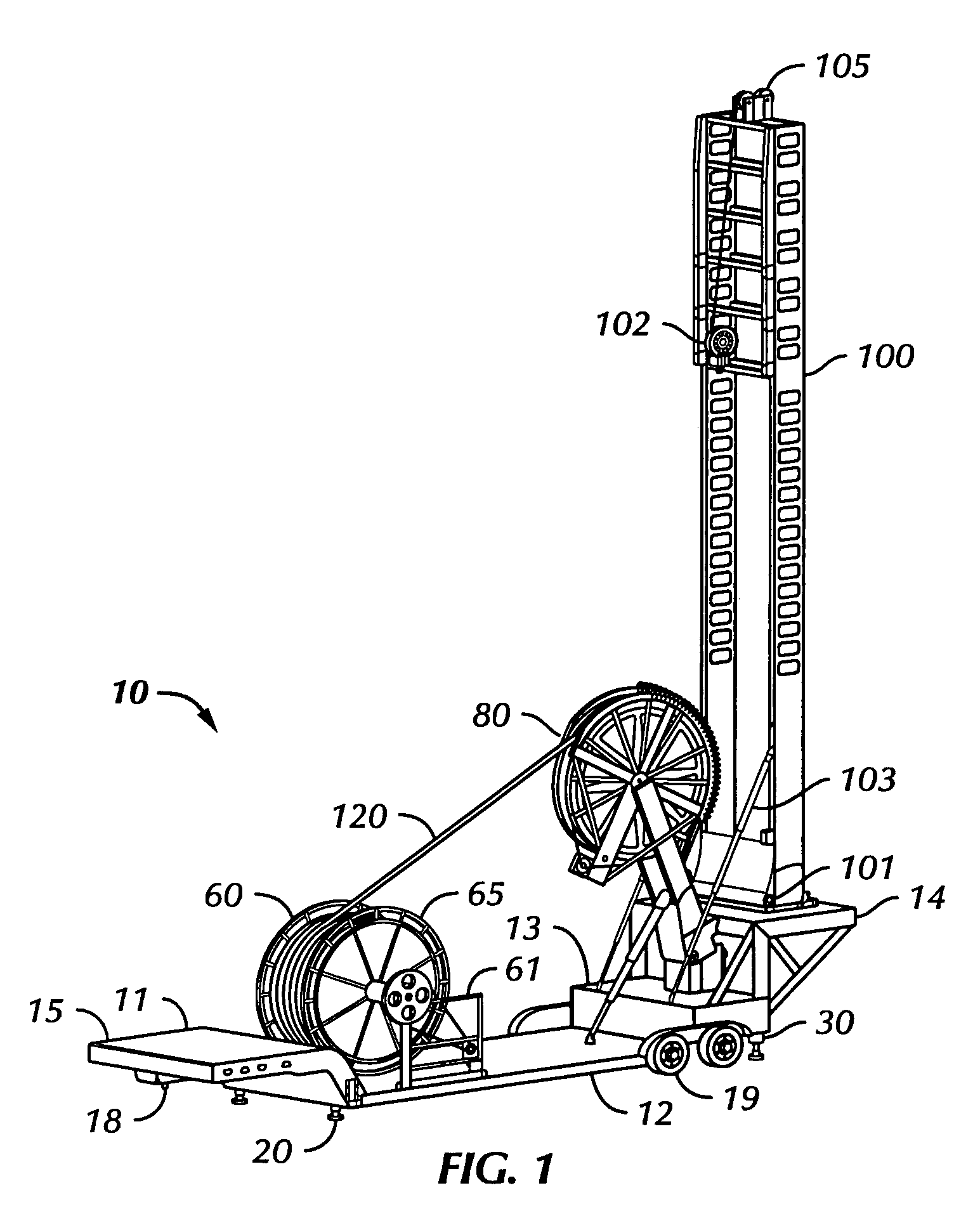
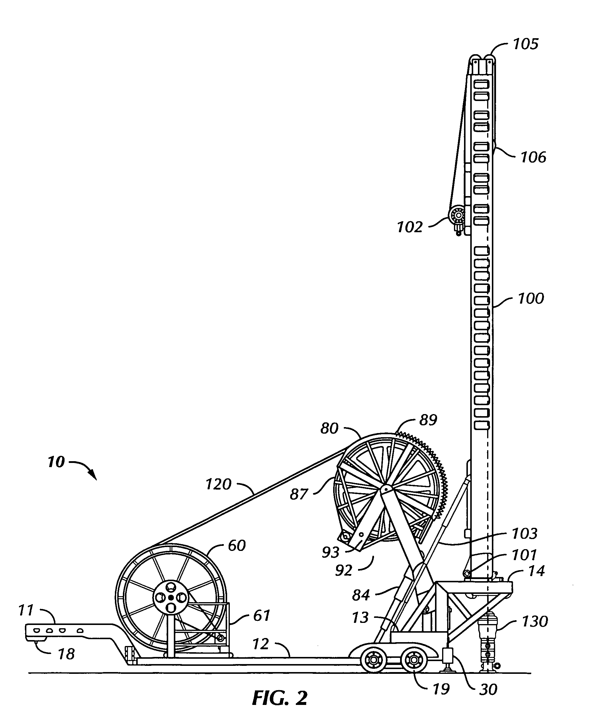
[0023]The combination drilling and workover rig of the present invention combines a capability to drill wells, as well as perform well maintenance and service, using either or both tubing with threaded tubular connections or coiled tubing. Some of the components used in this improved combination rig are well known in the oilfield. However, several of the components have been modified and the arrangement and operation of the components of the rig are unique and confer several advantages over rigs of conventional construction. A preferred embodiment of the combination drilling and workover rig is mobile being mounted on a truck or trailer bed.

[0024]Referring to FIG. 1 particularly, but also to FIGS. 2, 3, and 4, the improved mobile combination rig 10 is seen in two different operational positions and, in FIG. 4, its traveling configuration. As shown herein, the rig 10 is mounted on a modified conventional low-boy trailer 11 which has a dropped center section 12 and an elevated rear se...


PUM


Abstract

The combination workover and drilling rig of the present invention combines a capability to drill a well, as well as perform well maintenance and service, using either or both tubing with threaded tubular connections or coiled tubing. A mast and a coiled tubing injector are independently mounted to a support platform and can be operated independently of each other. The coiled tubing injector is selectably elevatable into a stowed position, a ready position, or an operating position.

Description

CROSS-REFERENCE TO RELATED APPLICATION[0001]The present application, pursuant to 35 U.S.C. 111(b), claims the benefit of the earlier filing date of provisional application Ser. No. 60 / 730,740 filed Oct. 27, 2005, and entitled “Combination Workover and Drilling Rig.”BACKGROUND OF THE INVENTION[0002]1. Field of the Invention[0003]The present invention relates to a workover and drilling rig for use in servicing and stimulating existing wells and drilling new wells for the production of fluids from subterranean formations. The present invention is particularly suited for use in oil and gas production.[0004]2. Description of the Related Art[0005]Truck or trailer-mounted conventional drilling and workover rigs are typically of either of two basic types. The first type, which is used for conventionally threaded tubulars, consists of the combination of a mobile supporting platform (e.g., a trailer or a truck bed) and an elevatable rig mast. The second type, which is used for coiled tubing, ...

Claims


Application Information

Patent Timeline
IPC IPC(8): E21B19/22E21B19/00
CPCE21B19/22
Inventor GIPSON, TOMMIE C.
Owner TOM C GIPSON
Why Eureka
Try Eureka