Optical connector with shutter

a technology of optical connectors and shutters, applied in the direction of optical elements, coupling device connections, instruments, etc., can solve the problems of increasing the accommodating space of shutters, the shaft cannot be extremely thin, and the entire connecter becomes large, so as to reduce the total thickness of connectors and facilitate formation

Inactive Publication Date: 2006-12-26
HOSIDEN CORP
View PDF7 Cites 128 Cited by
  • Summary
  • Abstract
  • Description
  • Claims
  • Application Information

AI Technical Summary

Benefits of technology

[0013]To achieve the above aim, an optical connector with a shutter according to the present invention includes a case including an inserting hole to which a plug of a fiber-optic cable is inserted, an optical element arranged at the back part of the inserting hole so as to be optically coupled with the plug inserted into the inserting hole of the case, an inward opening type shutter hinge-supported in the vicinity of an opening of the inserting hole and opening inward with the insertion of the plug into the inserting hole, and a shutter biasing spring arranged between a back surface of the shutter and the inner wall surface of the case so as to elastically support the shutter in the closed state and having one part or an entire part thereof sandwiched between the shutter and the inner wall surface of the case so as to be substantially coplanar when the shutter opens and lies along the inner wall surface of the case.
[0018]When the plate spring is used, the plate spring elastically deforms into a sheet of plate shape between the shutter and the inner wall surface of the case when the shutter opens and lies along the inner wall surface of the case. Thus, for the minimum necessary space thickness to accommodate the shutter in the opened position, only the plate thickness of the plate spring needs to be added to the shutter thickness, thereby enabling reduction in the accommodating space thickness.
[0020]The case is also preferably configured including a body with the wall surface of the side the shutter opens opened, and a cover attached to the body so as to block the opening. According to such a configuration, the shutter is accommodated within the opening of the body, and by having the cover as a thin metal cover, the wall thickness of the side the shutter opens is made thin, thereby reducing the total thickness of the connector. Further, by using the opening during body molding by metal mold, the convex part can be easily formed to lock the plug in the wall surface opposite the opening of the body.
[0021]The optical connector with a shutter according to the present invention has a configuration in which the shutter biasing spring for elastically holding the inward opening type shutter in a closed position is arranged between the back surface of the shutter and the inner wall surface of the case and one part of or entire part thereof is sandwiched so as to be substantially coplanar between the shutter and the inner wall surface of the case when the shutter opens and lies along the inner wall surface of the case, and thus even if the inward opening type shutter is used, the minimum necessary space thickness for accommodating the shutter in the opened position is made thin to nearly the shutter thickness, and the entire connector is effectively made small.

Problems solved by technology

The outer diameter of the coil part depends on the thickness of the hinge shaft of the shutter, and a size of a certain extent is required because the hinge shaft cannot be made extremely thin in terms of strength.
Thus, the accommodating space of the shutter increases, and further, the entire connecter becomes large.

Method used


Image

  • Optical connector with shutter
  • Optical connector with shutter
  • Optical connector with shutter

Examples


Embodiment Construction

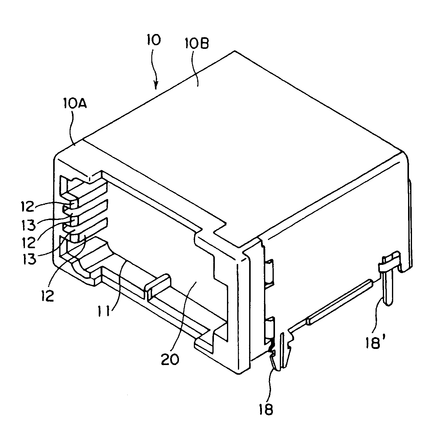
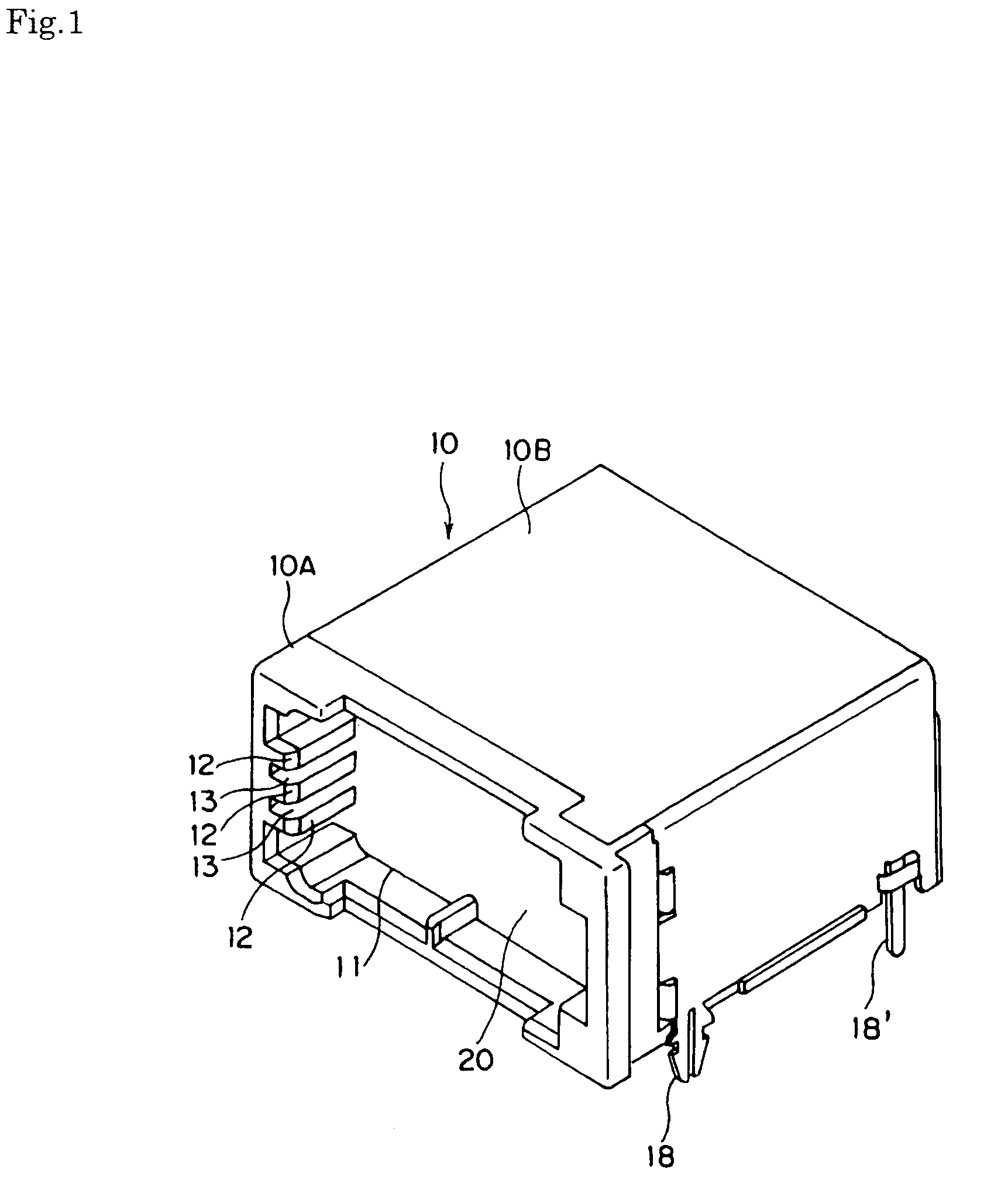
[0035]The embodiments of the present invention will now be explained based on the figures. FIG. 1 is a perspective view showing an optical connecter with shutter according to one embodiment of the present invention, FIG. 2 is a perspective view showing the optical connecter with shutter with the cover removed, FIG. 3 is a longitudinal side view of the optical connector with a shutter, FIG. 4 is a cross-sectional plan view of the optical connector with a shutter, FIG. 5 is a perspective view of a shutter biasing spring used in the optical connector with a shutter, and FIG. 6 is a longitudinal side view showing the opening state of the shutter of the optical connecter with shutter in steps.

[0036]The optical connector with a shutter according to the present embodiment is one type of LAN for automobiles, and is such in which the inward opening type shutter is attached to the optical connector complying with the MOST standard supporting the high-speed optical data link of in-vehicle mult...


PUM


Abstract

An optical connector with a shutter which minimizes the accommodating space for the shutter of inward opening type. The shutter opening inward in accordance with the insertion of the plug is provided near the inlet of the plug inserting hole of the case. A shutter biasing spring holding the shutter in the closed position is a torsion coil spring including a pair of arms projecting in two directions from the coil part. The shutter biasing spring is arranged so that the coil part faces towards the hole back side between the back surface of the shutter and the inner wall surface of the case. When the shutter opens and lies along the inner wall surface, both arms are sandwiched between the shutter and the inner wall surface of the case, and the coil part is positioned outside between the shutter and the inner wall surface of the case.

Description

BACKGROUND OF THE INVENTION[0001]1. Field of the Invention[0002]The present invention relates to optical connectors used in optical data transmission and, more specifically, to an optical connector with a shutter in which an inserting port to which a plug of a fiber-optic cable is inserted is opened and closed with the shutter.[0003]2. Description of the Related Art[0004]The optical connecter used in optical data transmission has a basic structure of a combination of a case including an inserting hole to which the plug of the fiber-optic cable is inserted and an optical element arranged at the back part of the inserting hole so as to be optically coupled with the plug inserted into the inserting hole of the case, on both a transmission side and a reception side.[0005]In such an optical connector, closing of an opening, that is, the inserting port of the inserting hole, is carried out with an openable and closable shutter to prevent foreign materials such as dust from entering the in...

Claims


Application Information

Patent Timeline
Patent Type & Authority Patents(United States)
IPC IPC(8): G02B6/36G02B6/38G02B6/42
CPCG02B6/4292G02B6/3831G02B2006/4297G02B6/4278
Inventor MINE, KEIJINAKAGAWA, HIROSHI
Owner HOSIDEN CORP
Why Eureka
Try Eureka