System and method for precision machining with a single point cutter

a single point cutter and precision machining technology, applied in the field of profile cutting methods and systems, can solve the problems of reducing throughput, increasing the complexity of the machine, and requiring more floor space, so as to enhance the ease of use of single point cutting machines and eliminate constraints

a single point cutter and precision machining technology, applied in the field of profile cutting methods and systems, can solve the problems of reducing throughput, increasing the complexity of the machine, and requiring more floor space, so as to enhance the ease of use of single point cutting machines and eliminate constraints

US7153073B2Active Publication Date: 2006-12-26HARMAND FAMILY PARTNERSHIP A CALIFORNIA PARTNERSHIP

Image

  • System and method for precision machining with a single point cutter
  • System and method for precision machining with a single point cutter
  • System and method for precision machining with a single point cutter

Examples


first embodiment

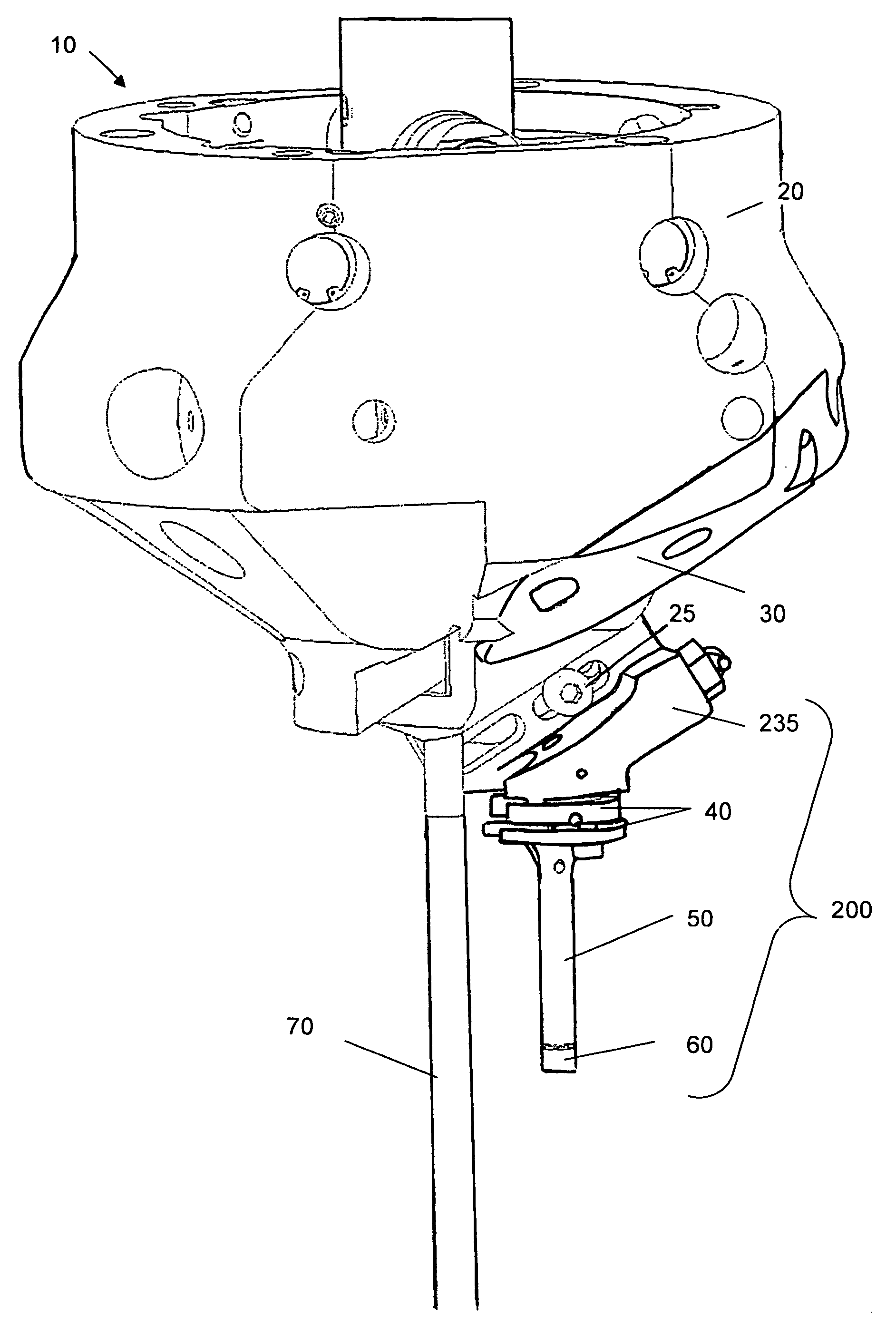
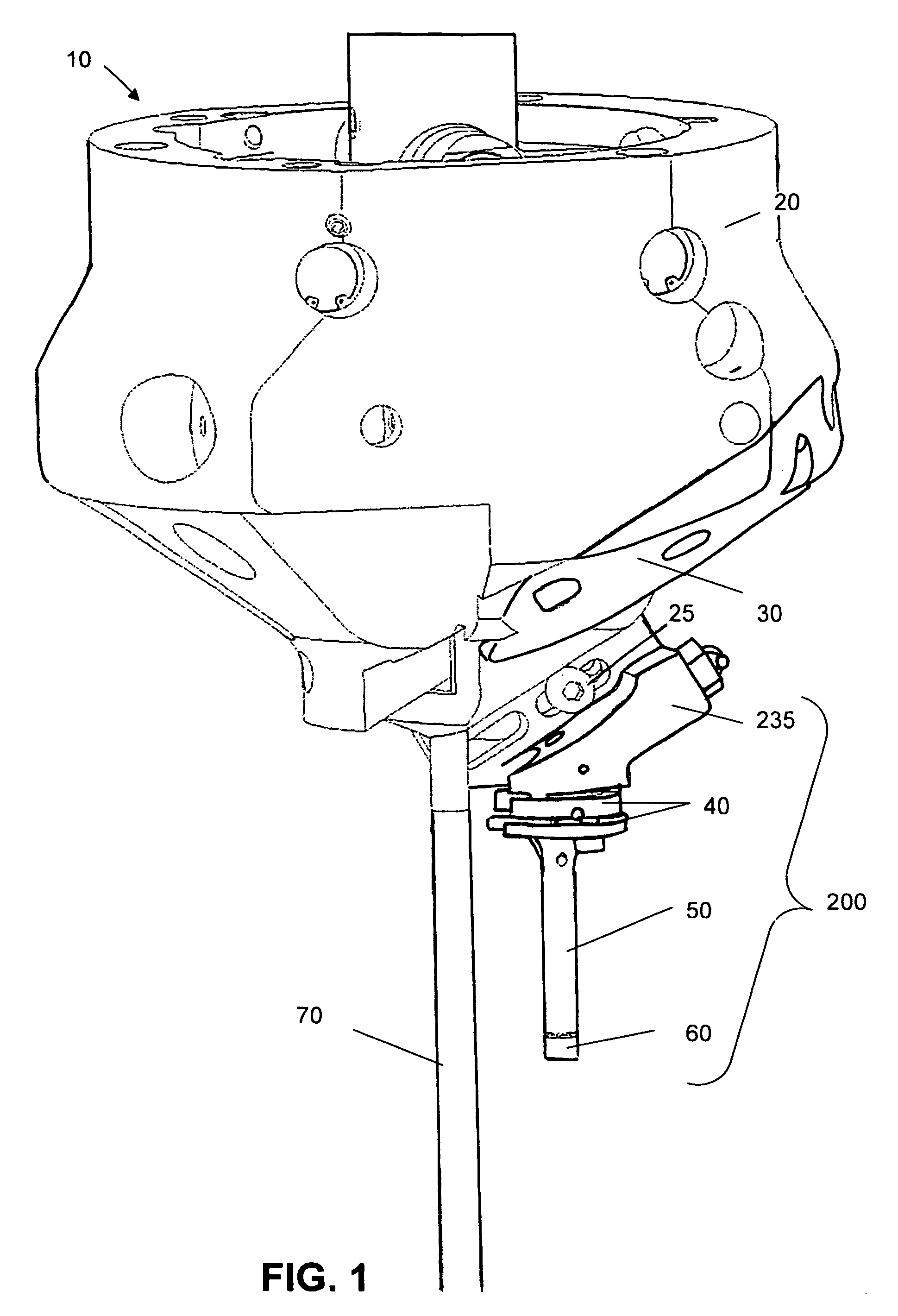
[0028]In the present invention, the utility and ease of use of single point cutting machines are enhanced by eliminating the constraint of having to draw a material profile. The system has the capacity to automatically duplicate the material profile with a precision of the order of 0.01 mm. The present invention uses a sensor 200 to determine the profile that is to be duplicated.

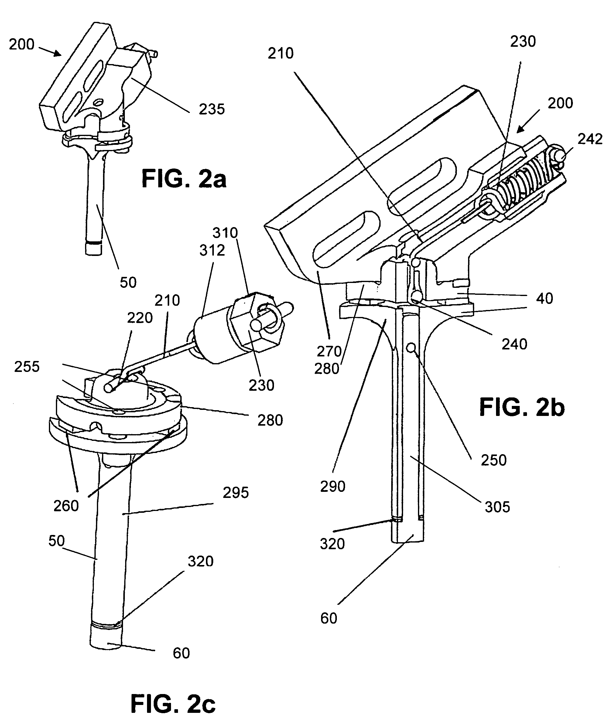
[0029]Illustrated in FIG. 1, in the exemplary embodiment, a sensor 200 is attached to the carriage 30 at the lower extent of the machining head 10, such as disclosed in U.S. Pat. No. 6,530,727. The sensor 200 is installed in a similar manner and in place of the cutting tool holder which would be installed during machining. The carriage feed driving assembly provides control of the inward and outward movement of the carriage head. The sensor is first mounted on the carriage head through one of a plurality of mounting holes to determine the profile that is to be cut into the material and feed the information t...

second embodiment

[0034]the sensor is illustrated in FIGS. 7–9. Sensor assembly 600 comprises a probe finger 601, lower piezo plate 608, upper support 614 and piezoelectric chips 610. Three chips 610 are shown, however, there may be as few as one chip or more than three chips. The chips 610 are uniformly radially spaced within circular recess 615 in support 614. Support 614 also supports RF antenna 620.

[0035]Probe finder 601 has three main sections: distal section 602, center section 604 and proximal section 606. Distal section 602 and proximal section 606 has substantially equal diameters, while center section 604 has a reduced diameter to allow the probe finger to flex to prevent damage if the contact surface 605 of distal section 602 inadvertently impacts against the work surface with excessive force.

[0036]The proximal end 609 of probe finger 601 inserts into a corresponding bore 607 in lower piezo plate 608. Preferably, bore 607 and proximal end 609 are threaded so that probe finger 601 can be ea...


PUM

PropertyMeasurementUnit
surface topographyaaaaaaaaaa
pressureaaaaaaaaaa
electricalaaaaaaaaaa

Abstract

The single point machining head includes a probe that is removably mounted on a carriage that moves radially relative to a central axis of the machining head. A system controller moves the carriage in a radial direction while the machining head is fed in a vertical direction so that the probe contacts the surface of a workpiece. Each point of contact on the workpiece becomes a datapoint including the radial position and the vertical position when contact occurred. The surface of the workpiece is scanned with the probe and a profile is generated using the points of contact. A system controller calculates a difference between the measured profile and a desired profile to be machined to determine the amount of material to remove.

Description

RELATED APPLICATIONS[0001]This application claims the priority of U.S. provisional application No. 60 / 593,096, filed Dec. 9, 2004, which is incorporated herein by reference.FIELD OF THE INVENTION[0002]The invention generally relates to a method and system for cutting a profile in a workpiece using a single point cutting head and the ability to automatically determine a cutting profile in the workpiece.BACKGROUND OF THE INVENTION[0003]Machining of materials to create openings or recesses of different shapes is used in the manufacture and repair of a wide range of objects. In applications where the dimensional tolerances, roundness and smoothness of the machined surface are important, special tools are often required, especially when the material to be machined is very hard or otherwise difficult to machine. For example, transfer machines within an automated manufacturing line often require multiple machining heads with a variety of different cutting bits to form rounded openings of t...

Claims


Application Information

Patent Timeline
26 Dec 2006
Publication
US7153073B2
IPC
B23C3/00
CPC
B23C3/055; B23C3/056; B23Q17/20; B23Q17/2233; Y10T409/307336; Y10T409/303864; Y10T82/2502; Y10T483/14
Inventors
HARMAND, BRICE; HARMAND, PIERRE