Method and apparatus for protection of wildlife from contact with power phase cutout mechanism

a technology of power phase cutout and protection method, which is applied in the direction of maintaining distance between parallel conductors, hot sticks switches, circuit arrangements, etc., can solve the problems of severe injury, inability to find current flowing through the conductor, and rarely provided any type of electrical barrier between energized components and other objects in electric distribution systems

Active Publication Date: 2006-12-26
ECO ELECTRICAL SYST LLC
View PDF8 Cites 32 Cited by
  • Summary
  • Abstract
  • Description
  • Claims
  • Application Information

AI Technical Summary

Problems solved by technology

An increasingly sensitive environmental issue is that of preventing injury to wildlife that may occur as a result of contact with energized electrical distribution components.
Modernly, electrical distribution systems rarely provided any type of electrical barrier between energized components and other objects.
This is because the small bird contacts only one electrical conductor and the current flowing through the conductor cannot find a “path to ground”.
It is only when a living creature, including man or beast, contacts an exposed electrical conductor or other energized component and electrical current can find a path to ground that severe injury can occur.
This type of unfortunate incident is more likely to occur where exposed electrical conductors are in close proximity to a grounded object or to another conductor or component that is carrying an opposite phase of a particular circuit.
In such case, the living creature is in close enough proximity to ground by virtue of being in contact with the power pole that the slightest contact with an exposed electrical conductor or other energized component may prove fatal.
Larger birds, such as raptors, are often killed when they land on or attempt to land on an exposed electrical conductor near a power-pole or on the power-pole itself.
This results in a short circuit where electrical current flows through the body of the unfortunate bird from one phase to the other.
The entire cutout assembly poses a threat not only to wildlife, but also to lineworkers.
This is because the upper and lower contact assemblies are not insulated.
As soon as the raptor contacts the non-insulated, energized cutout assembly it can be severely injured or killed.

Method used


Image

  • Method and apparatus for protection of wildlife from contact with power phase cutout mechanism
  • Method and apparatus for protection of wildlife from contact with power phase cutout mechanism
  • Method and apparatus for protection of wildlife from contact with power phase cutout mechanism

Examples


Embodiment Construction

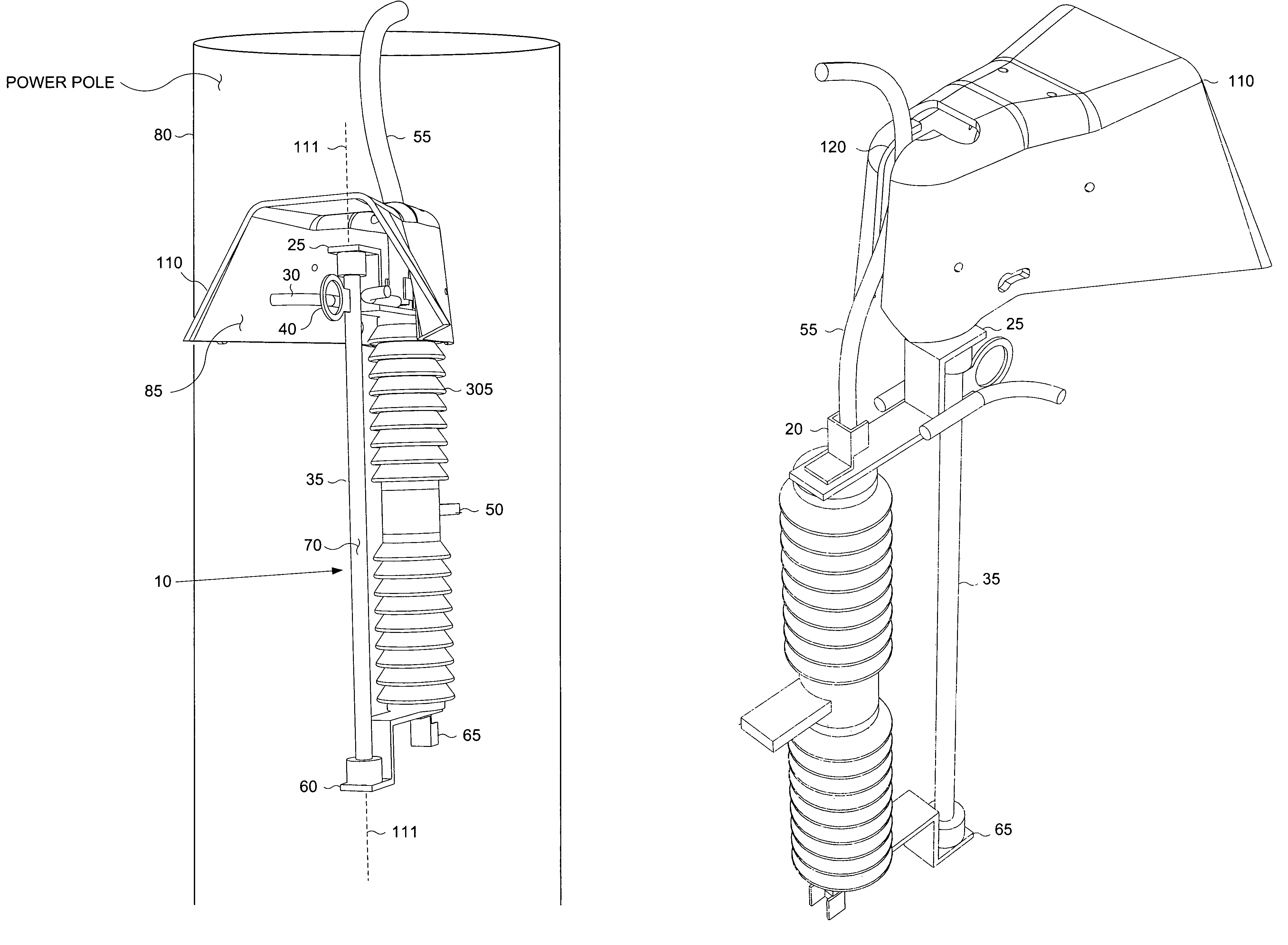
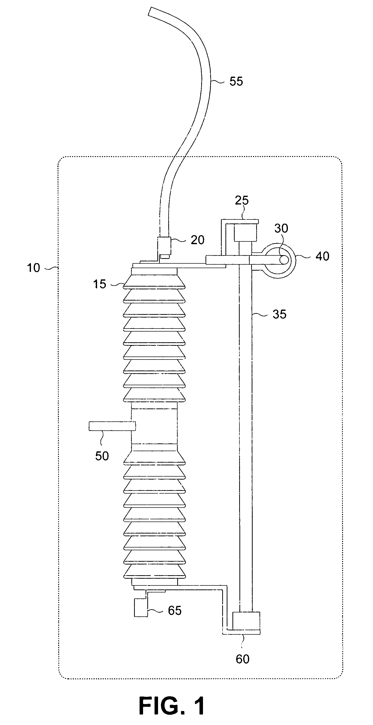
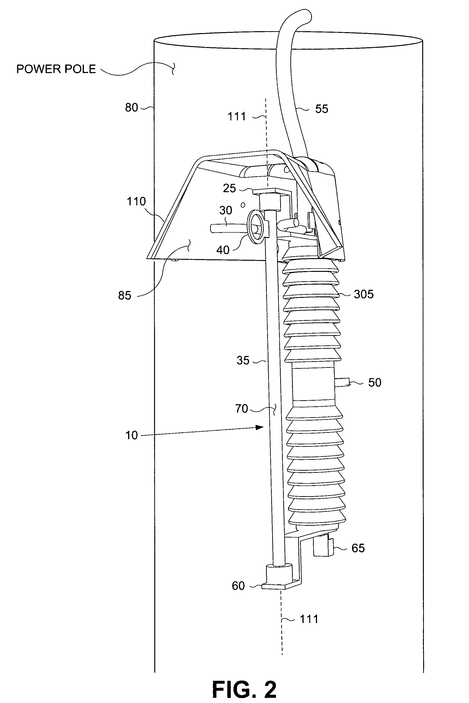
[0026]FIG. 1 is a pictorial representation of an electrical cutout assembly. Electrical power distribution systems disseminate electrical power through a distribution grid. When power is delivered from the distribution grid, it is normally received at a very high voltage. The high-voltage power is generally transformed to a lower voltage by a transformer before it is delivered to a power consumer such as a home or a business. It should be noted that these two classes of power consumers are cited as example users of a typical power distribution system and are not intended to limit the scope of the present invention.

[0027]It is not uncommon for a distribution system to distribute electrical power at voltage levels; as high as 69,000 volts and more. A cutout 10 comprises an insulator 15 which is used to support an upper contact assembly 25. The upper contact assembly usually includes an upper connector 20. The insulator 15 is used to provide electrical isolation between the upper conta...


PUM


Abstract

Method and apparatus for protecting wildlife from contact with an energized fuse assembly known as a “cutout”, also known as a “disconnect”. The cutout is shrouded from above and three sides. One side is left open to facilitate installation or removal of a fuse holder assembly. The shroud is formed to allow the use of a hot-stick for installation and removal of a fuse holder assembly into a fuse receptacle formed by upper and lower contact assemblies held in opposition to each other by an insulator. The shroud provides a slot enabling installation when a wire is connected to the upper contact assembly. A pin is used to hold the shrouding in place.

Description

RELATED APPLICATIONS[0001]This present application is related to a provisional application Ser. No. 60 / 435,836 filed on Dec. 19, 2002, entitled “Method and Apparatus for Protection of Wildlife from Contact with Power Phase Cutout Mechanism”, by Lynch, currently pending, for which the priority date for this application is hereby claimed.FIELD OF THE INVENTION[0002]This invention relates generally to protection of wildlife environments; and specifically to a prevention of electrocution or shock resulting from contact with power cutout or disconnect mechanisms.BACKGROUND OF THE INVENTION[0003]An increasingly sensitive environmental issue is that of preventing injury to wildlife that may occur as a result of contact with energized electrical distribution components. Modernly, electrical distribution systems rarely provided any type of electrical barrier between energized components and other objects. For instance, electrical conductors that carry electrical power from power-pole to powe...

Claims


Application Information

Patent Timeline
Patent Type & Authority Patents(United States)
IPC IPC(8): H02B1/06H01H31/00
CPCH01H31/006
Inventor LYNCH, MICHAEL D.
Owner ECO ELECTRICAL SYST LLC
Why Eureka
Try Eureka