
Media drive vibration isolation and attenuation method and apparatus

a technology of media drives and vibration isolation, which is applied in the field of media drives, can solve the problems of unconstrained, significant challenges in the implementation of disk drives, and errors that affect the input/output speed of individual disk drives and the system, and achieve the effect of reducing the number of disk drives

Active Publication Date: 2006-12-26
ORACLE INT CORP
View PDF8 Cites 14 Cited by
  • Summary
  • Abstract
  • Description
  • Claims
  • Application Information

AI Technical Summary

Benefits of technology

This patented technology describes an improved way to protect electronic components from damage caused by external impacts during transportation or storage. It involves mounting two separate parts onto different surfaces: a main part called a computer chip with its own memory device(RAM) inside it; another component called a disc drive connected through cables between them. A special type of reinforce bar can be used along these lines - also known as a reinforcement rail – to keep both devices stable even if they hit each other accidentally due to collisions.

Problems solved by technology

The technical problem addressed in this patent text is the need for a method and apparatus to isolate and attenuate shock and vibration in a disk module that includes media drives that are mounted on a printed circuit board (PCB). This is necessary to prevent problems such as poor mounting solutions, unconstrained disk drive vibrations, and external shocks and vibrations from affecting the performance and reliability of the disk drives.

Method used


Image

  • Media drive vibration isolation and attenuation method and apparatus
  • Media drive vibration isolation and attenuation method and apparatus
  • Media drive vibration isolation and attenuation method and apparatus

Examples


Embodiment Construction

[0032]A preferred embodiment of the present invention and its advantages are better understood by referring to the figures, like numerals being used for like and corresponding parts of the accompanying figures.

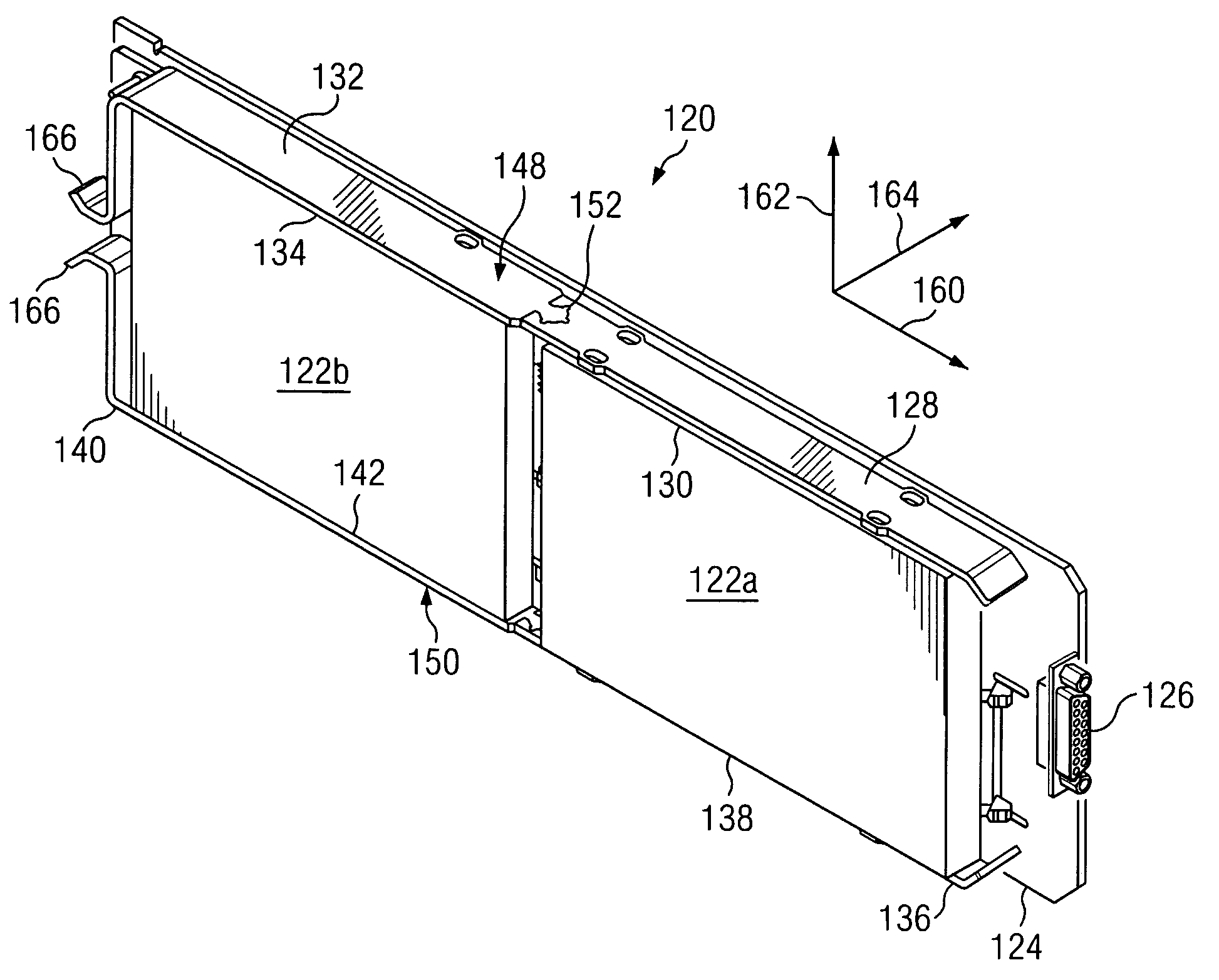
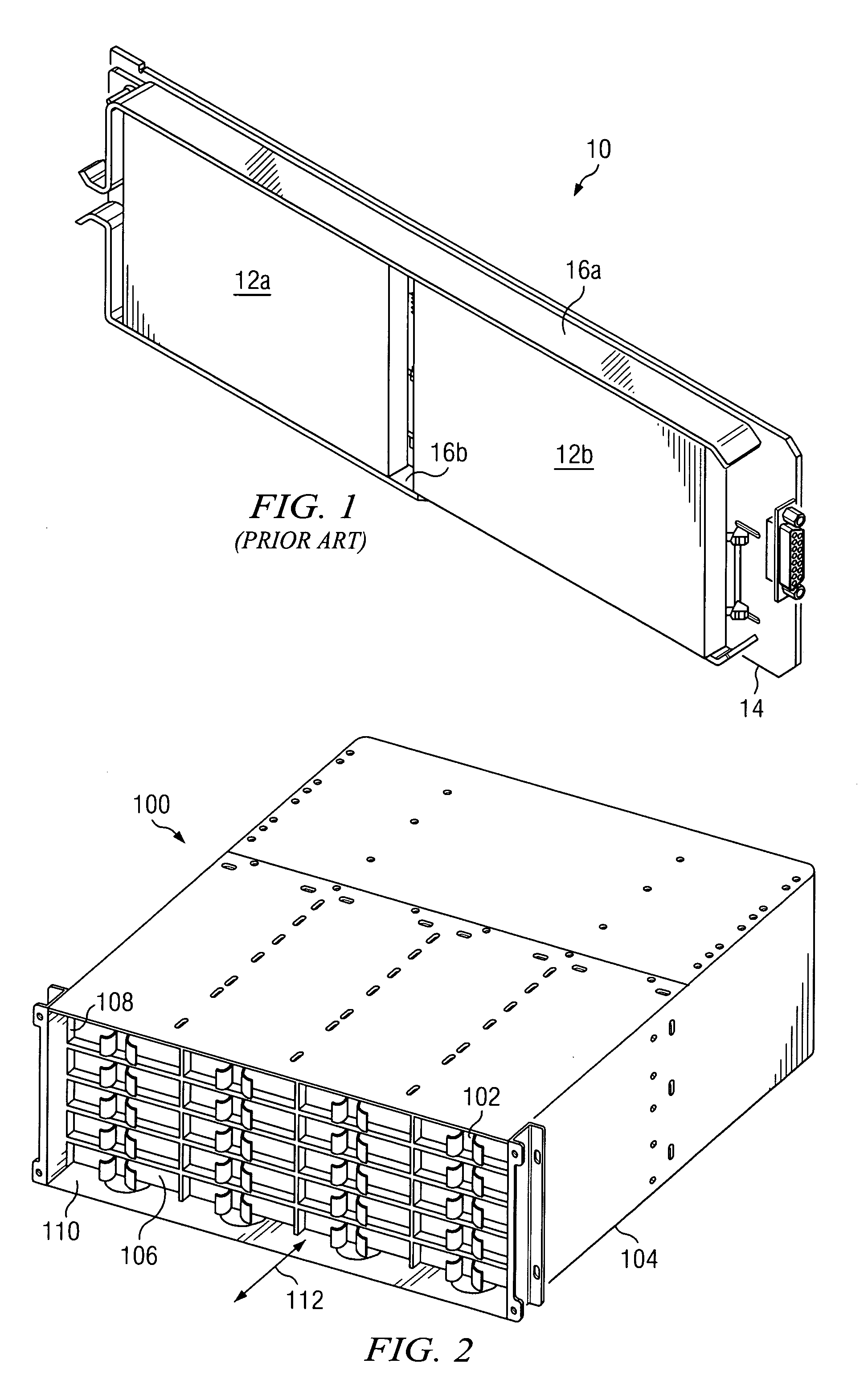
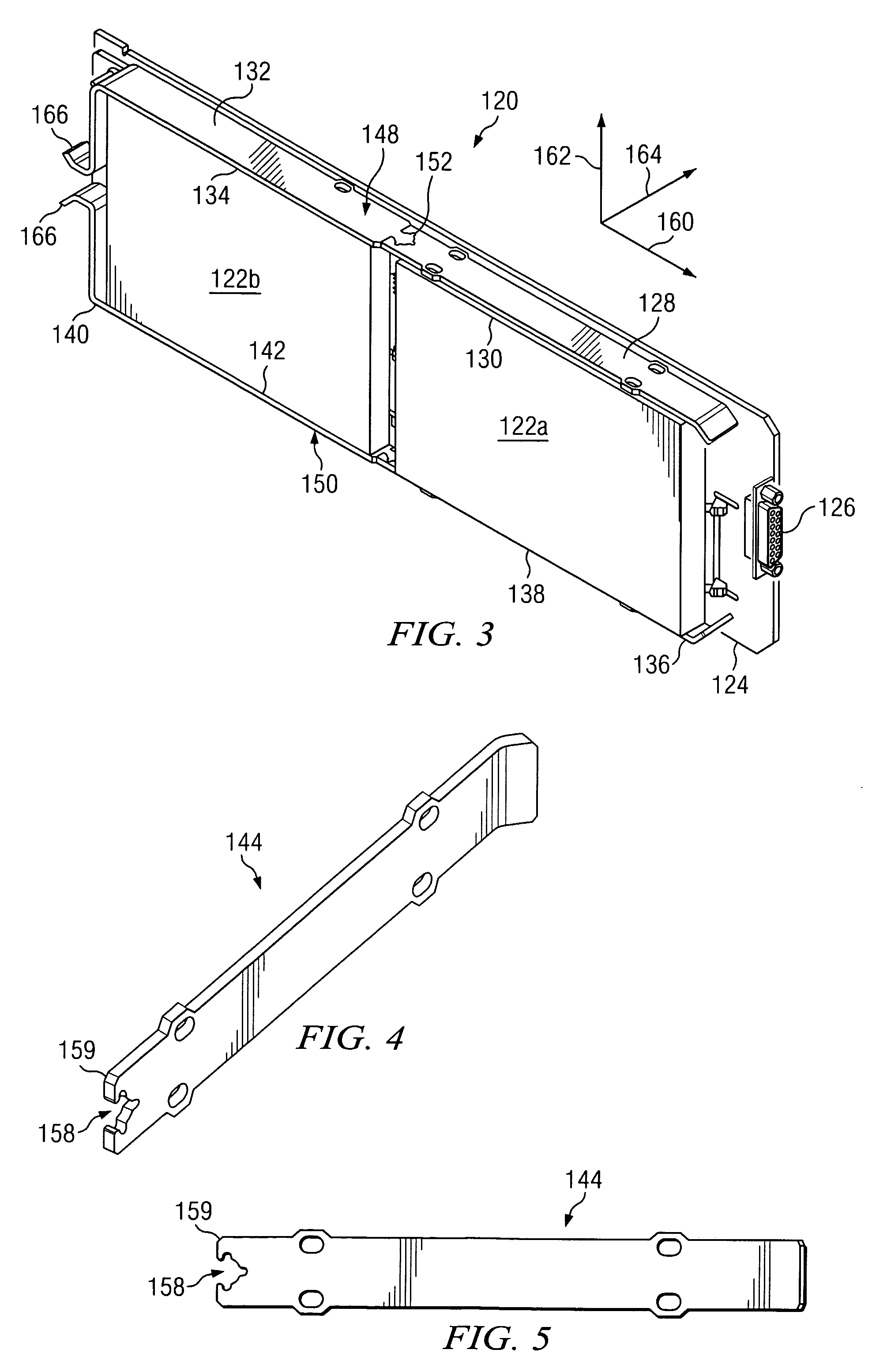
[0033]The present invention is a method and apparatus for isolating and attenuating shock and vibration in a disk module that includes media drives that are mounted on a printed circuit board (PCB). The apparatus includes a single printed circuit board (PCB), media drives that are coupled to the PCB, a first reinforcing rail that is attached to the PCB and to a first side of a first one of the media drives, a second reinforcing rail that is attached to the PCB and to a first side of a second one of the media drives, and a locking mechanism for locking the first and second rails together.

[0034]FIG. 2 is a perspective view of an example system implementing the present invention. An example system 100 that implements the present invention for multiple media drives 102 is shown in...


PUM


Abstract

A method and apparatus are disclosed for isolating and attenuating shock and vibration in a disk module that includes media drives that are mounted on a printed circuit board (PCB). The apparatus includes a single printed circuit board (PCB), media drives that are coupled to the PCB, a first reinforcing rail that is attached to the PCB and to a first side of a first one of the media drives, a second reinforcing rail that is attached to the PCB and to a first side of a second one of the media drives, and a locking mechanism for locking the first and second rails together.

Description


Claims


Application Information

Patent Timeline
Owner ORACLE INT CORP
Learn More