Spraying gun

a technology of spraying gun and spraying nozzle, which is applied in the direction of spraying apparatus, liquid spraying apparatus, spray nozzle, etc., can solve the problems of user inconvenience in changing and adjusting the spraying manner limiting and user's clothes easily wet, so as to prevent the injected water from wetting and enhance the versatility of the conventional spraying gun

a technology of spraying gun and spraying nozzle, which is applied in the direction of spraying apparatus, liquid spraying apparatus, spray nozzle, etc., can solve the problems of user inconvenience in changing and adjusting the spraying manner limiting and user's clothes easily wet, so as to prevent the injected water from wetting and enhance the versatility of the conventional spraying gun

US7156325B1Inactive Publication Date: 2007-01-02SHIN TAI SPURT WATER OF THE GARDEN TOOLS

Image

  • Spraying gun
  • Spraying gun
  • Spraying gun

Examples


Embodiment Construction

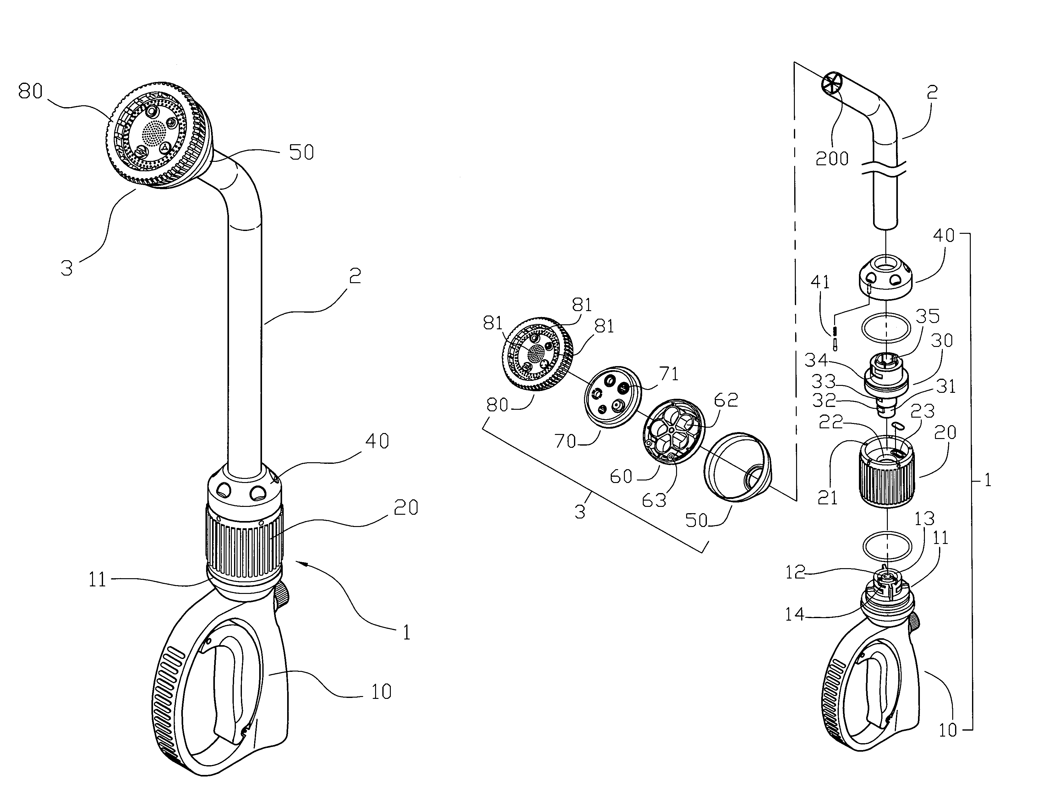
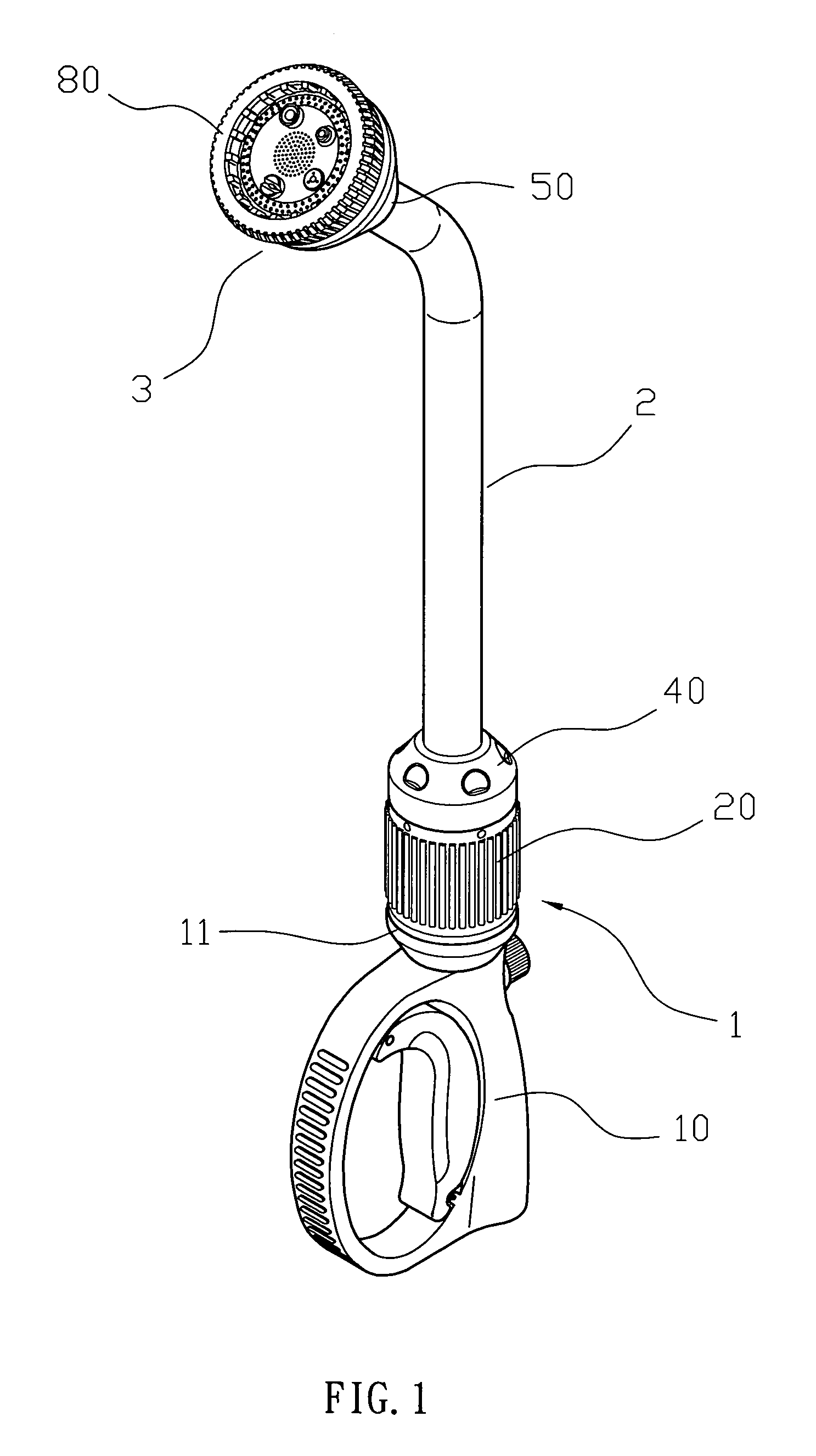
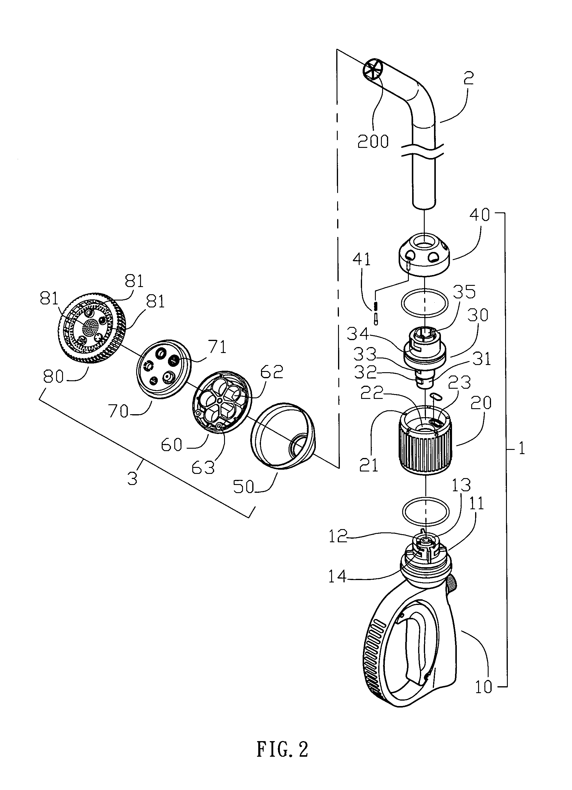
[0022]Referring to the drawings and initially to FIGS. 1–3, a spraying gun in accordance with the preferred embodiment of the present invention comprises a water guide pipe 2 having an inside formed with a plurality of water channels 200, a control unit 1 mounted on a first end of the water guide pipe 2, and an injection unit 3 mounted on a second end of the water guide pipe 2.

[0023]The control unit 1 includes a feeding member 10, a fitting member 30, an adjusting member 20, and a jacket 40.

[0024]The feeding member 10 of the control unit 1 is connected to a water source (not shown) and has an end provided with a mounting portion 11 having an inside formed with a water outlet 12 and a periphery formed with an annular groove 13 having a locking cavity 14.

[0025]The fitting member 30 of the control unit 1 is mounted on the mounting portion 11 of the feeding member 10 and has a first end 31 inserted into the groove 13 of the mounting portion 11 of the feeding member 10 and formed with a ...


PUM


Abstract

A spraying gun includes a water guide pipe, a control unit, and an injection unit. The injection unit includes a water guide member, a water control plate, a water injection ring, and a shade. Thus, the control unit can control the water to flow into different water channels of the water guide pipe, and the injection unit has corresponding water inlet hole, water outlet hole, water filling hole and nozzle to align with the respective water channel of the water guide pipe, so that different kinds of water flow are injected outward from the nozzles of the injection unit so as to change the sprinkling manner of the spraying gun.

Description

BACKGROUND OF THE INVENTION[0001]1. Field of the Invention[0002]The present invention relates to a spraying gun, and more particularly to a spraying gun having a control unit that can adjust the sprinkling manner of the spraying gun.[0003]2. Description of the Related Art[0004]A conventional spraying gun comprises a gun body having an inside formed with a water channel having a first end connected to a water inlet pipe and a second end connected to a nozzle having a plurality of water outlet holes. The water from the water inlet pipe is introduced into the water channel and is injected outward from the water outlet holes of the nozzle. However, the water from the water inlet pipe is injected outward from the water outlet holes of the nozzle constantly, so that the sprinkling manner of the conventional spraying gun is fixed and cannot be adjusted, thereby limiting the versatility of the conventional spraying gun.[0005]Another conventional spraying gun comprises a water guide pipe hav...

Claims


Application Information

Patent Timeline
02 Jan 2007
Publication
US7156325B1
IPC
A62C31/02
CPC
B05B1/1636
Inventors
CHEN, CHIN-YUAN