

Rotary valve in a multi-gas cooker
- Summary
- Abstract
- Description
- Claims
- Application Information
AI Technical Summary
Benefits of technology
Problems solved by technology
Method used
Image

Examples
Embodiment Construction
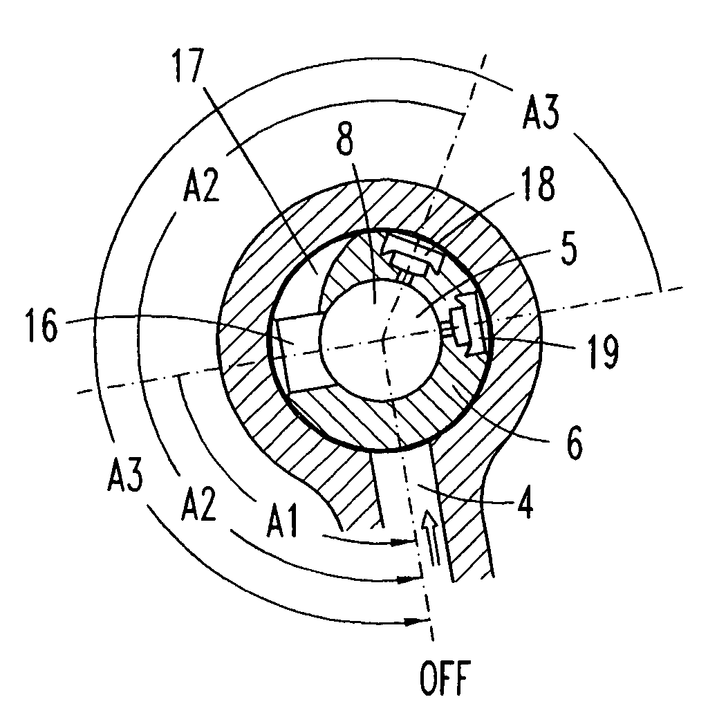
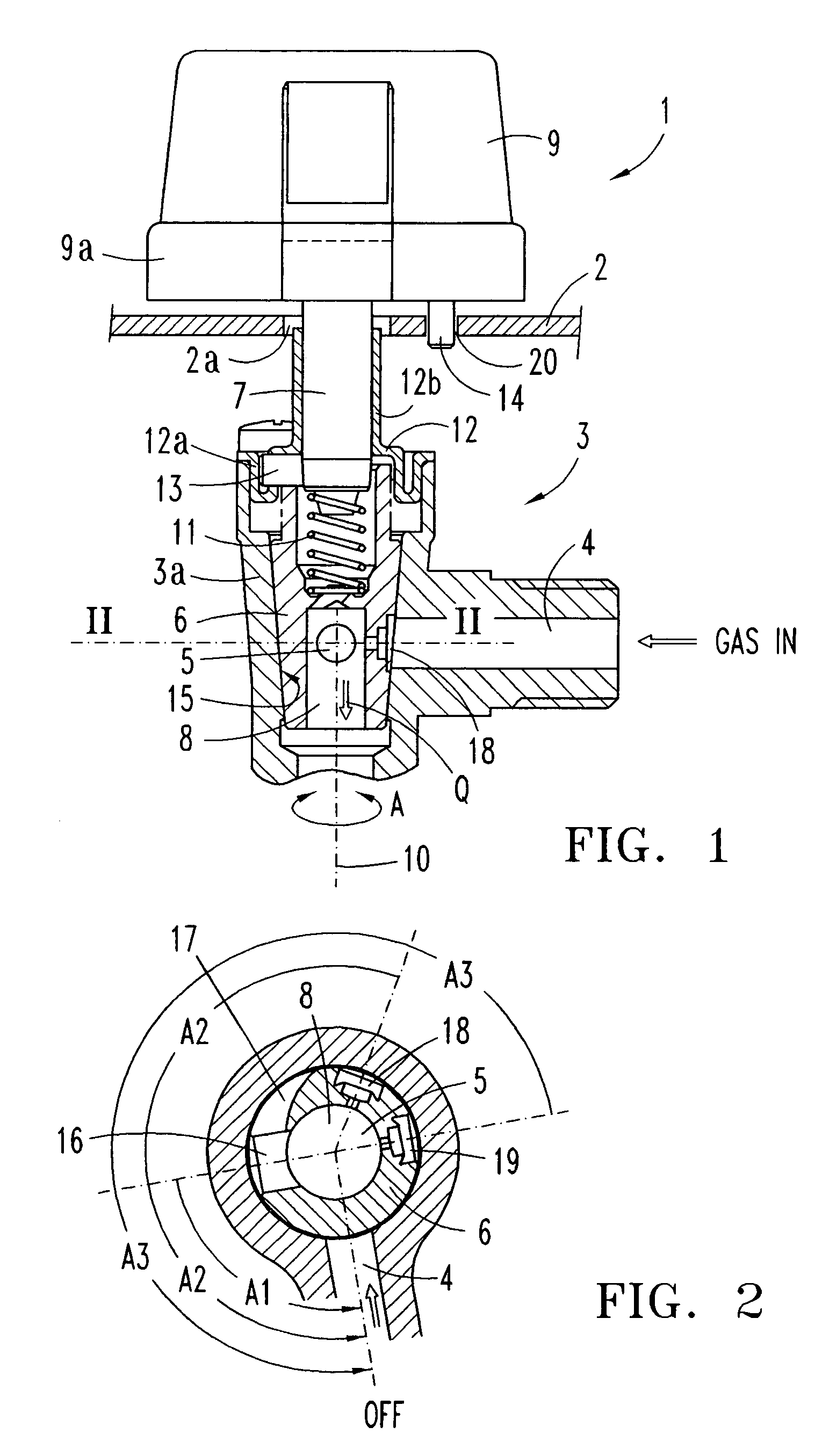
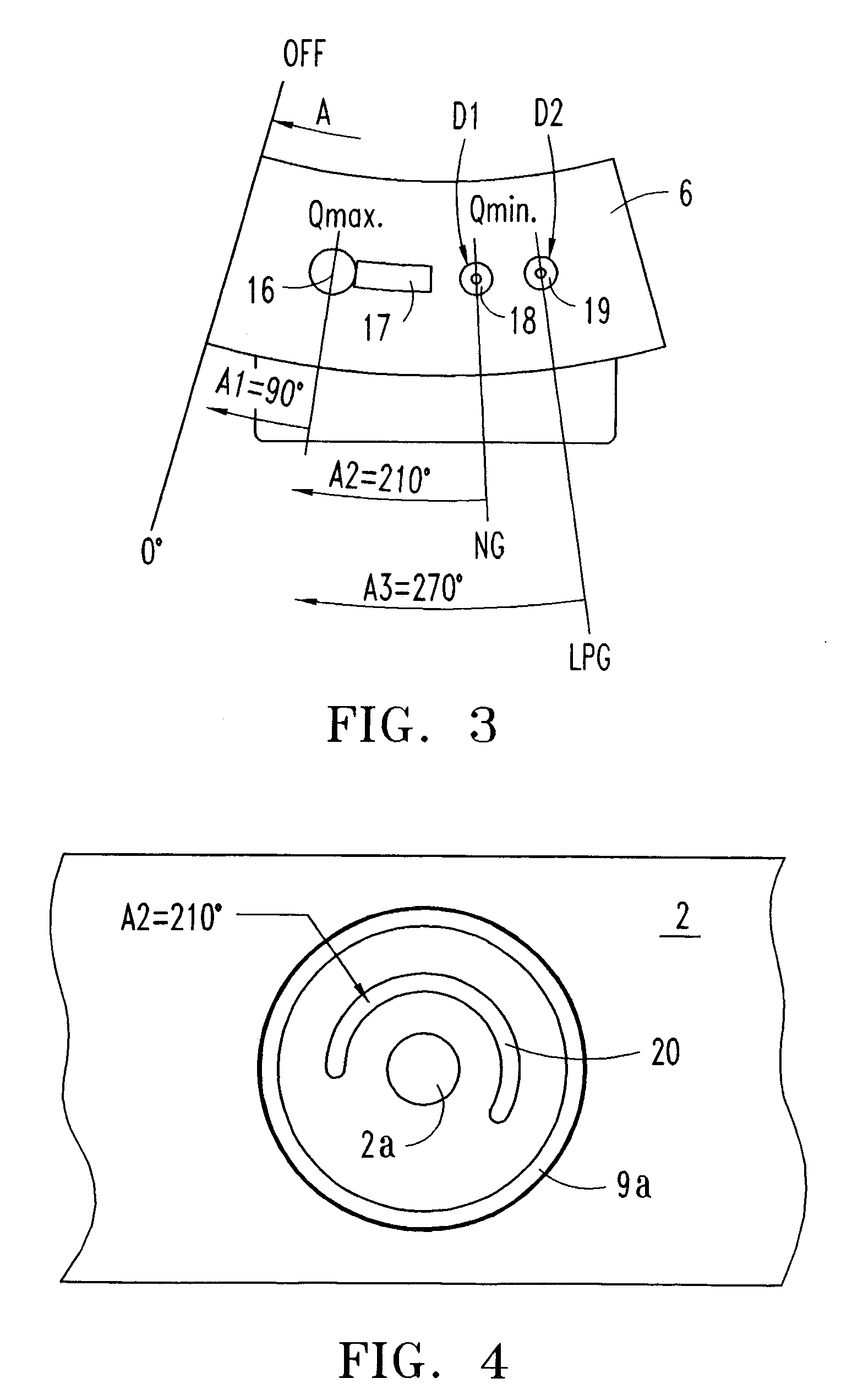
[0014]With reference to FIGS. 1–4, an embodiment of a gas cooking appliance 1 such as a barbecue has a control panel 2 on which are mounted one or more rotary gas valves of an existing general type. The cooking appliance 1 may be of two types in respect of the type of gas supplied, natural gas (NG) or liquefied gas (LPG) from the external source—GAS IN—through a valve inlet conduit 4 in the valve body 3a. Each one of the valves 3 mounted on the panel 2 is always of a single type, all with a same valve body 3a and a same frusto-conical regulating organ 6. The inlet flow “Q” is transmitted to an internal chamber 8 in regulating organ 6 in communication with an outlet conduit 5 in the valve body 3a. The regulating organ 6 rotates around a central axis 10 actuated by shaft 7 for the supply of the flow “Q”, which is directed towards a burner on the appliance (not shown in the drawings), being the latter specifically adapted to either N gas or LP gas.
[0015]The valve body 3a has an elongat...
PUM
 Abstract
Description
Claims
Application Information