[0019]In this aspect of the invention, cutter damage as a result of “chipping” can be reduced by ensuring the
radius of the retracted movable cutter(s) is slightly greater than the cutter
radius of the
drill bit so that the movable cutter(s) is / are always in contact with the formation being drilled whether they are in their radially extended or retracted position
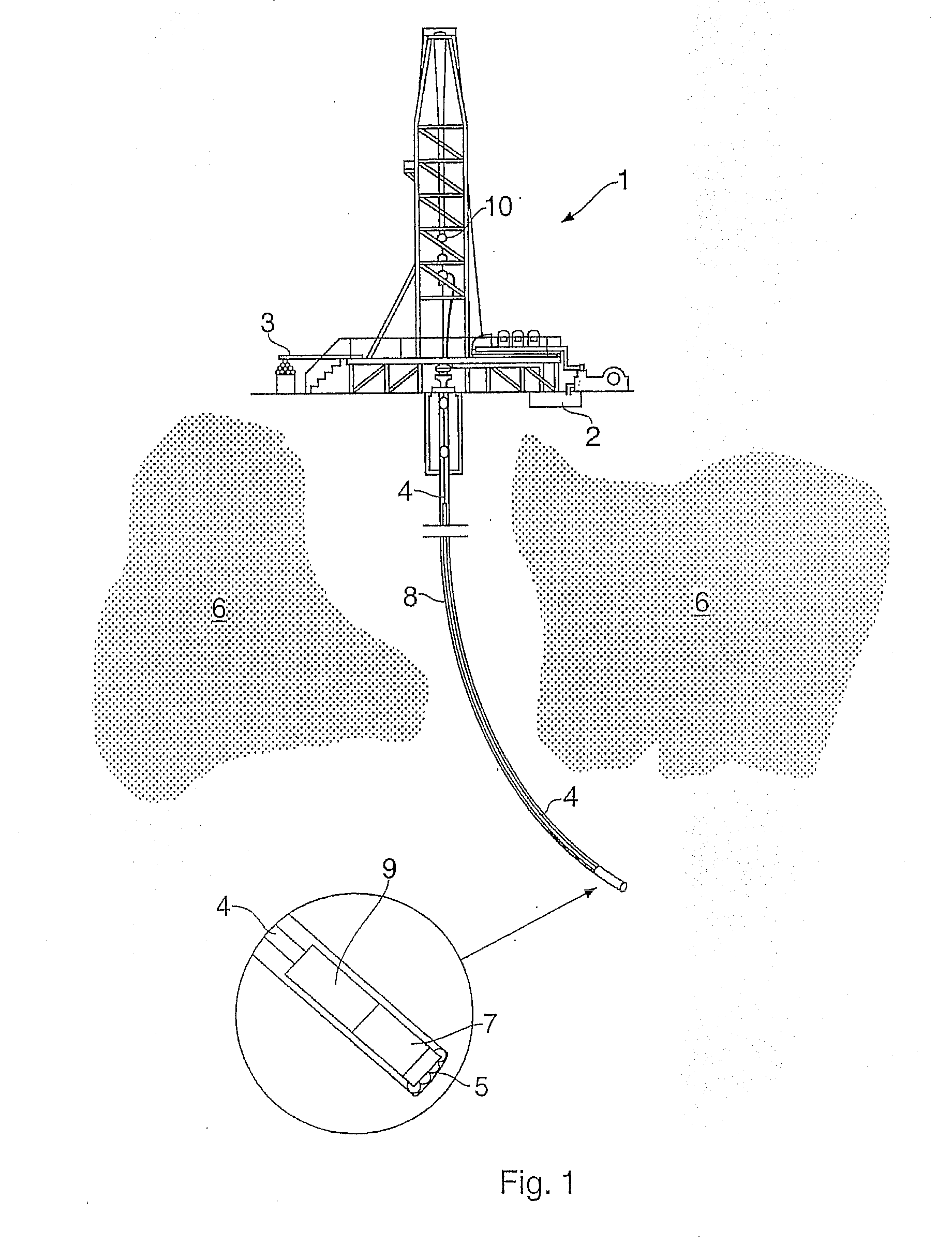
[0020]According to another aspect of the present invention, there is provided a method of controlling the direction of the drilling axis of a rotatable boring
drill bit of a
drill string comprising a plurality of hollow drill collars on a drilling end of which the bit is mounted, at least one cutter being mounted on or in the collar adjacent the
drill bit for rotation with
drill string, the at least one cutter being mounted for movement between a first radially extended position and a second retracted position, and the method comprising the steps of drilling a substantially circular cross section
pilot bore hole having a
radius determined by the cutting radius of the drill bit, controllably moving the at least one cutter as the drill is rotated so that movement of the movable cutter is synchronized with rotation of the drill so that the movable cutter continuously engages the wall of the
pilot bore hole to enlarge the hole as the movable cutter rotates, wherein the synchronized movement of the movable cutter causes the cross-section of the bore hole to become non-circular and form a
linear channel parallel to the drilling axis.
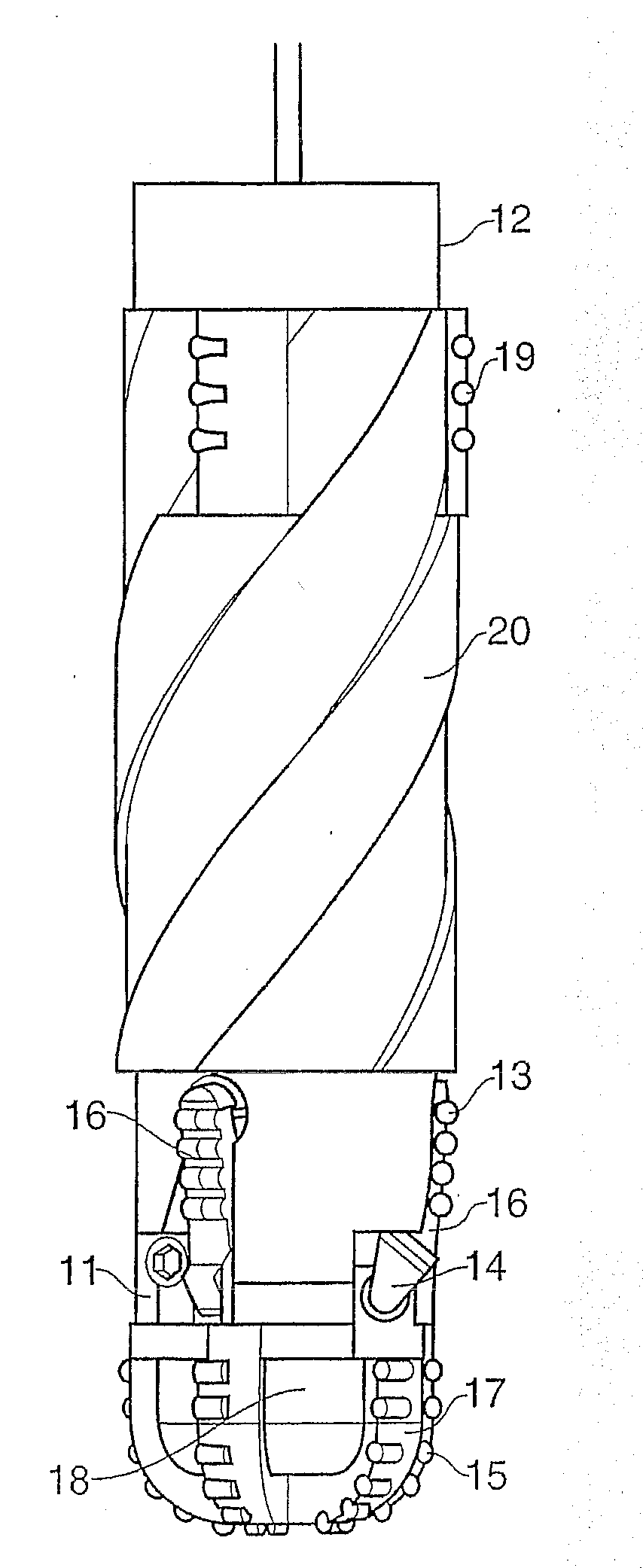
[0022]Control of the directional
drilling system is affected by the synchronized movement of movable drilling cutter(s) from an inner to outer
radial position in accordance with the angular position of the drill bit. For example, by deploying the dynamic cutters over a 240° period, an eccentric channel about the longitudinal axis of the BHA, and parallel thereto, will be produced. As drilling progresses, a near bit stabilizer, located above and behind the dynamic cutters, contacts with the portion of well bore which was not removed with the dynamic cutters, i.e., the concentric part or
pilot hole
cut by drill bit cutters on the tip of the drill body. This contact exerts a force onto the near bit stabilizer which is reacted by the drill bit and another stabilizer or drill bit further up the
drill string. The reaction force between the drill bit and the formation results in a side
cutting force on the drill bit and hence deviation of the drill bit is achieved.
[0027]According to another aspect of the invention there is provided a directional drilling device for use in drilling boreholes, the device being positionable between a drill bit and associated drill collar of a drill string having a longitudinal drilling axis; the device comprising: at least one cutting member movably mounted with respect to a body member, the cutting member(s) being movable between a first radially extended position for engagement with the wall of a bore hole and a second radially retracted position, and means for directing pressurized fluid to the region between the body member and the cutter. Preferably, directional control means are provided for
synchronizing the movement of the cutting member(s) between the respective extended and retracted positions in accordance with the rotational position of the body member in the bore hole being drilled. Preferably, at least one fluid exit port or
nozzle is provided in the drilling tool body to direct pressurized
drilling fluid from an internal passageway within the tool body to the region behind the moveable cutter or cutters. In this way, the exiting pressurized fluid provides a cleaning jet to flush away cutting debris that may otherwise gather between the body member of the drilling tool and the moveable cutter(s) and thereby prevent the build up of debris which may otherwise prevent the moveable cutter(s) returning to the retracted position.
[0031]According to another aspect of the present invention, there is provided a directional drilling device for controlling the drilling direction of a rotary drill bit when drilling boreholes in subsurface formations; the device being positionable at or towards the end of a drill string for rotation with the drill string about a longitudinal drilling axis; the device comprising: a rotatable body including a drill bit or means for connecting a drill bit to the body at a down hole end thereof for rotation with the body about a longitudinal drilling axis; at least one directional cutting member movably mounted with respect to the body; the directional cutting member being movable radially with respect to the longitudinal axis of the body for engagement with the wall of a borehole
cut by the drill bit such that the geometric center of the cutting member may be aligned substantially coincident with the axis of rotation of the body member or radially offset therefrom by relative radial movement such that the movable cutter is capable of following an eccentric path with respect to the body member and drill bit as the body member and drill bit rotate during drilling to selectively enlarge the bore hole cut by the drill bit; and, directional control means for synchronizing the radial movement of the cutting member in accordance with the rotational position of the body in the bore hole being drilled. Preferably, the cutting member comprises a cylindrical element disposed around the exterior of the body member. This aspect of the invention readily enables the directional cutting member to support relatively large lateral cutting loads in use.
[0032]The present invention relates to a directional drilling apparatus for use in the directional drilling of bore holes. In one embodiment the apparatus comprises a plurality of cutting elements movably mounted with respect to a rotatable body member, wherein the cutting elements are movable between first, radially retracted, positions and radially extended, positions for cutting. A
rotary valve is provided for synchronizing the movement of the cutting elements between their respective extended and retracted positions in accordance with the rotational position of the body member in the bore hole being drilled. Control of the directional
drilling system is affected by synchronized movement of the cutting elements from an inner to an outer
radial position in accordance with the angular position of the drill bit. For example, by deploying the dynamic cutters over a 240° period, an elongate arcuate channel parallel to the longitudinal axis of the BHA will be produced. As drilling progresses a near bit stabilizer contacts with the portion of the well bore which was not removed with the dynamic cutters and this contact exerts a force onto the drill bit. The force causes the drill bit to cut sideways and hence deviation of the drill bit is achieved. Embodiments are disclosed in which means are provided for directing
high pressure cutting fluid to the region between the cutting elements and the rotatable body to prevent the accumulation of cutting debris in that region that could prevent movement of the cutting elements. Other embodiments are disclosed wherein the cutting elements enlarge the pilot bore hole formed by the drill bit so that the cutting elements continuously engage the wall of the pilot bore hole. Another embodiment is disclosed in which a cutting ring is provided which can be moved eccentrically with respect to the longitudinal drilling axis of the rotatable body.

