Apparatus and Systems Having a Rotary Valve Assembly and Swing Adsorption Processes Related Thereto

a technology of rotary valve and swing adsorption, which is applied in the direction of separation process, dispersed particle separation, chemical apparatus and processes, etc., can solve the problems of inefficient conventional systems for swing adsorption and the inability of swing adsorption systems to properly manage the void space within the condui

Active Publication Date: 2014-08-07
EXXONMOBIL UPSTREAM RES CO
View PDF5 Cites 50 Cited by
  • Summary
  • Abstract
  • Description
  • Claims
  • Application Information

AI Technical Summary

Benefits of technology

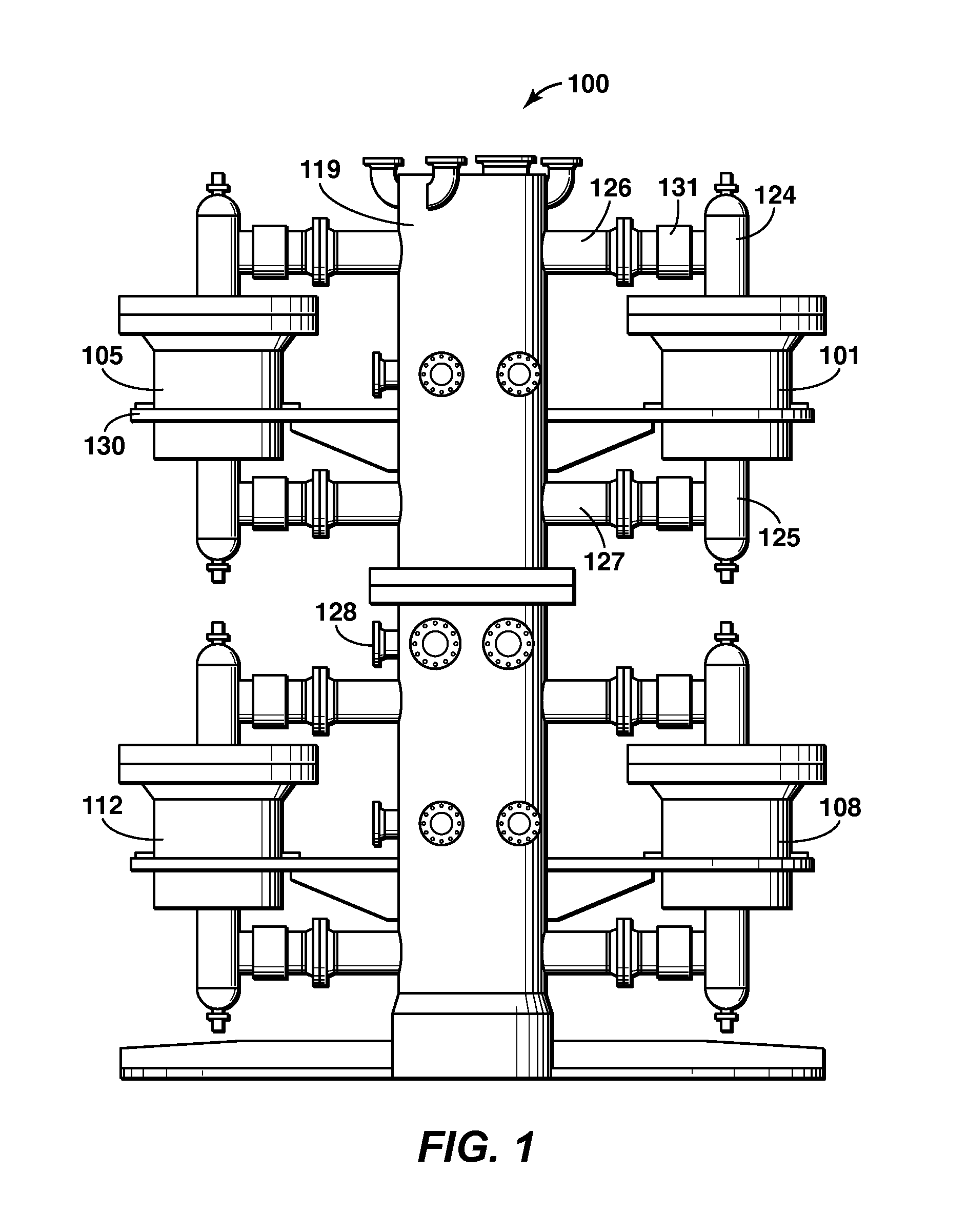
[0013]The swing adsorption system may also include additional rotary valve assemblies. For example, the system may include a second rotary valve assembly and a second plurality of reciprocating valve assemblies, wherein each of the second plurality of reciprocating valve assemblies is in fluid communication with the second rotary valve assembly via a dedicated conduit and is in fluid communication with one of plurality of adsorbent bed units. In this system, the rotary valve assembly and the second rotary valve assembly are each associated with different streams in the system. Alternatively, the system may include a second rotary valve assembly; and a second plurality of reciprocating valve assemblies, wherein each of the second plurality of reciprocating valve assemblies is in fluid communication with the second rotary valve assembly via a dedicated conduit and is in fluid communication with one of a second plurality of adsorbent bed units. The second rotary valve assembly may be disposed on a first tier and the rotary valve assembly is disposed on a second tier, wherein the second tier is at a higher elevation relative to the first tier.
[0014]In certain embodiments, the rotary valve assembly may include additional components. For example, the rotary valve assembly may include a drive assembly configured to rotate an aperture plate to provide the fluid to one or more of the plurality of reciprocating valve assemblies. The drive assembly may include a drive shaft, a sealed collar and wherein the plurality of transmitter magnets are disposed along the drive shaft and configured to rotate with the drive shaft. Also, rotary valve assembly may include at least one transmitter magnet and a plurality of receiver magnets, wherein at least one of the plurality of receiver magnets is associated with one of the plurality of reciprocating valve assemblies and is in communication with a sensor configured to transmit a signal to one of the plurality of reciprocating valve assemblies.
[0015]In one or more embodiments, a method of processing a feed stream is described. The method includes a) passing a feed stream through a rotary valve assembly; b) passing the feed stream from the rotary valve assembly to one of a plurality of reciprocating valve assemblies based on the alignment of an aperture plate in the rotary valve assembly; c) processing the feed stream from the one of a plurality of reciprocating valve assemblies in an adsorbent bed unit dedicated to the one of a plurality of reciprocating valve assemblies to separate one or more contaminants from the feed stream to form a product stream; d) conducting away from the adsorbent bed unit the product stream; e) rotating one or more components in the rotary valve assembly to a subsequent alignment, wherein the subsequent alignment stops fluid flow to the one of a plurality of reciprocating valve assemblies from the rotary valve assembly and permits fluid flow to a subsequent one of the plurality of reciprocating valve assemblies; f) processing the feed stream from the subsequent one of a plurality of reciprocating valve assemblies in a subsequent adsorbent bed unit dedicated to the subsequent one of a plurality of reciprocating valve assemblies to separate one or more contaminants from the feed stream to form a product stream; and g) conducting away from the subsequent adsorbent bed unit the product stream; and h) repeating the steps a-g for at least one additional cycle. The method may also include rotating at least one transmitter magnet relative to a plurality of receiver magnets, wherein at least one of the plurality of receiver magnets is associated with one of the plurality of reciprocating valve assemblies and is in communication with a sensor configured to transmit a signal to one of the plurality of reciprocating valve assemblies.

Problems solved by technology

However, swing adsorption systems do not properly manage the void space within the conduits of the system.
Accordingly, the conventional systems for swing adsorption are inefficient in managing the streams passing through the system in the various steps of the cycle.

Method used


Image

  • Apparatus and Systems Having a Rotary Valve Assembly and Swing Adsorption Processes Related Thereto
  • Apparatus and Systems Having a Rotary Valve Assembly and Swing Adsorption Processes Related Thereto
  • Apparatus and Systems Having a Rotary Valve Assembly and Swing Adsorption Processes Related Thereto

Examples


Embodiment Construction

[0021]Unless otherwise explained, all technical and scientific terms used herein have the same meaning as commonly understood by one of ordinary skill in the art to which this disclosure pertains. The singular terms “a,”“an,” and “the” include plural referents unless the context clearly indicates otherwise. Similarly, the word “or” is intended to include “and” unless the context clearly indicates otherwise. The term “includes” means “comprises.” All patents and publications mentioned herein are incorporated by reference in their entirety, unless otherwise indicated. In case of conflict as to the meaning of a term or phrase, the present specification, including explanations of terms, control. Directional terms, such as “upper,”“lower,”“top,”“bottom,”“front,”“back,”“vertical,” and “horizontal,” are used herein to express and clarify the relationship between various elements. It should be understood that such terms do not denote absolute orientation (e.g., a “vertical” component can be...


PUM


Abstract

Provided are apparatus and systems having a rotary valve assembly integrated with a reciprocating valve assembly to perform swing adsorption processes. The rotary valve assembly is utilized with the reciprocating valve assembly to manage the flow of streams through the system in an enhanced manner.

Description

CROSS REFERENCE TO RELATED APPLICATIONS[0001]This application claims the benefit of U.S. Patent Application No. 61 / 448,117 entitled APPARATUS AND SYSTEMS HAVING AN ENCASED ADSORBENT CONTACTOR AND SWING ADSORPTION PROCESSES RELATED THERETO, filed Mar. 1, 2011; U.S. Patent Application No. 61 / 448,120 entitled APPARATUS AND SYSTEMS HAVING A RECIPROCATING VALVE HEAD ASSEMBLY AND SWING ADSORPTION PROCESSES RELATED THERETO, filed Mar. 1, 2011; U.S. Patent Application No. 61 / 448,121 entitled METHODS OF REMOVING CONTAMINANTS FROM A HYDROCARBON STREAM BY SWING ADSORPTION AND RELATED APPARATUS AND SYSTEMS, filed Mar. 1, 2011; U.S. Patent Application No. 61 / 448,123 entitled APPARATUS AND SYSTEMS HAVING A ROTARY VALVE ASSEMBLY AND SWING ADSORPTION PROCESSES RELATED THERETO, filed Mar. 1, 2011; and U.S. Patent Application No. 61 / 594,824, entitled METHODS OF REMOVING CONTAMINANTS FROM A HYDROCARBON STREAM BY SWING ADSORPTION AND RELATED APPARATUS AND SYSTEMS, filed Feb. 3, 2012, each of which is h...

Claims


Application Information

Patent Timeline
Patent Type & Authority Applications(United States)
IPC IPC(8): B01D53/047
CPCB01D53/047B01D53/0446B01D53/0462B01D2259/40005
Inventor TAMMERA, ROBERT F.ANDERSON, THOMAS N.
Owner EXXONMOBIL UPSTREAM RES CO
Why Eureka
Try Eureka