
Rotary valve with internal leak control system

Active Publication Date: 2007-02-08
AIR PROD & CHEM INC
View PDF17 Cites 55 Cited by
  • Summary
  • Abstract
  • Description
  • Claims
  • Application Information

AI Technical Summary

Benefits of technology

[0058] (b) rotating the first and second rotors in sealing contact with the first and second stators, respectively, and maintaining the pressure in the interior volum

Problems solved by technology

Rigid materials such as metal, carbon, or ceramic typically are used for rotors and stators, but wear of the parts or distortions caused by temperature differentials may cause changes in the shape of the surfaces, thereby allowing leakage across the seal formed between the surfaces.
If there is leakage between ports at different pressures, cross-contamination may occur, which in turn can reduce PSA performance parameters such as product purity and product recovery.
Internal leakage among valve ports connected to the product ends of the beds is undesirable, because contaminants in the product ends of the beds can affect product purity.
When the PSA cycle includes regeneration and purge steps under vacuum, the pressure differentials across the valve sealing face, particularly between rotor and stator ports connecting the feed and product ends of the beds, may lead to various operating problems if leaks occur between these ports.

Method used


Image

  • Rotary valve with internal leak control system
  • Rotary valve with internal leak control system
  • Rotary valve with internal leak control system

Examples


Embodiment Construction

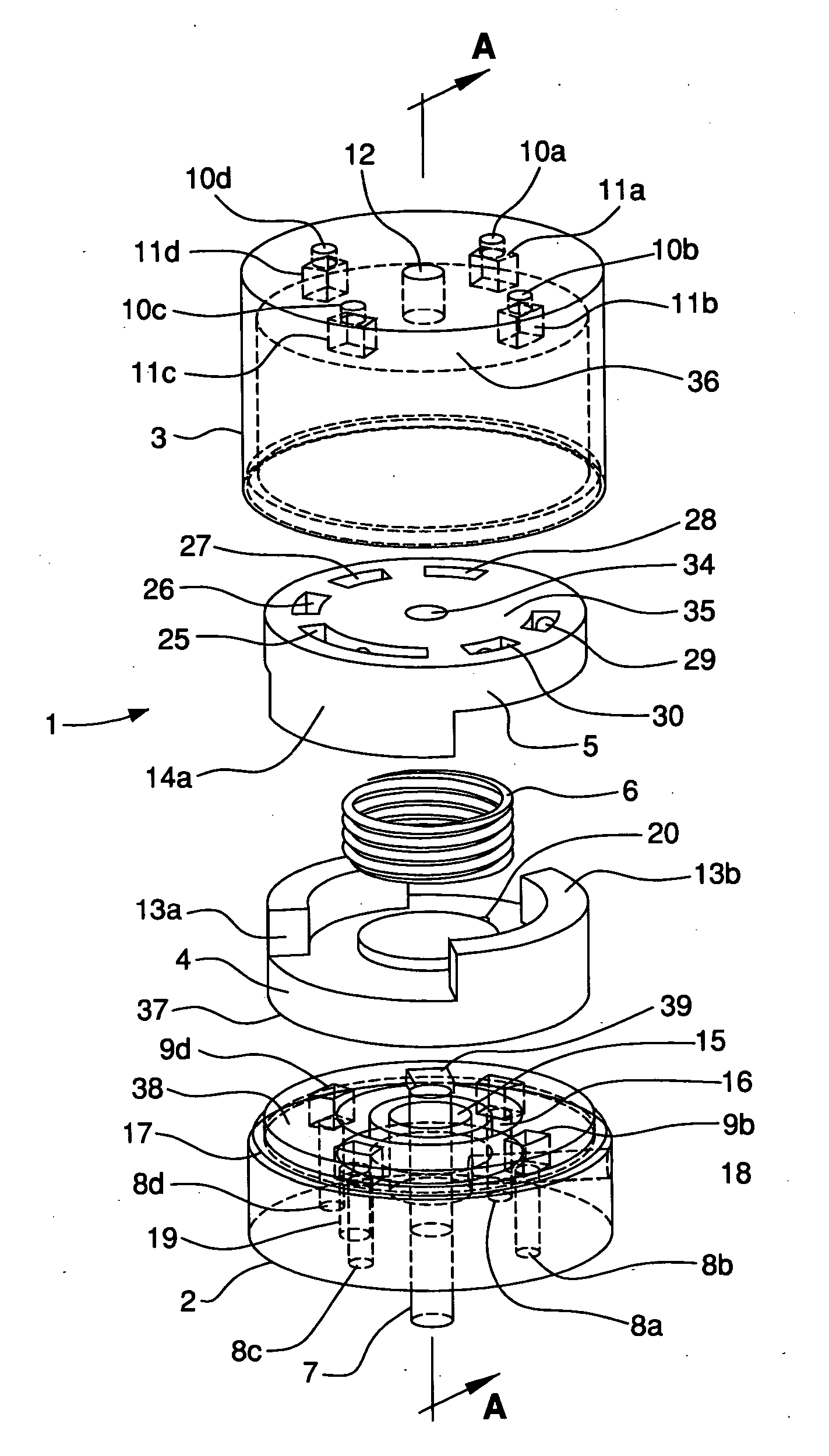
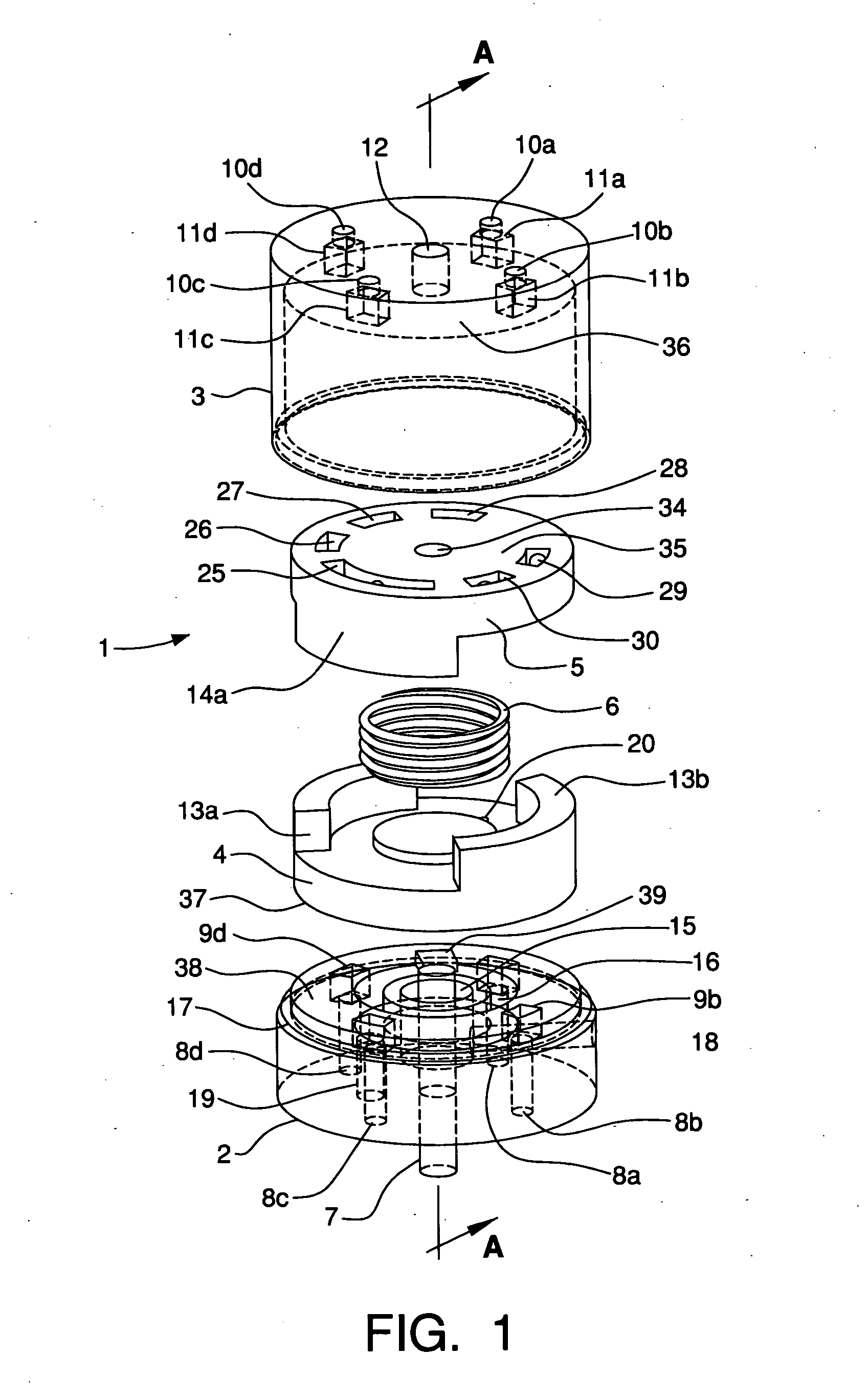
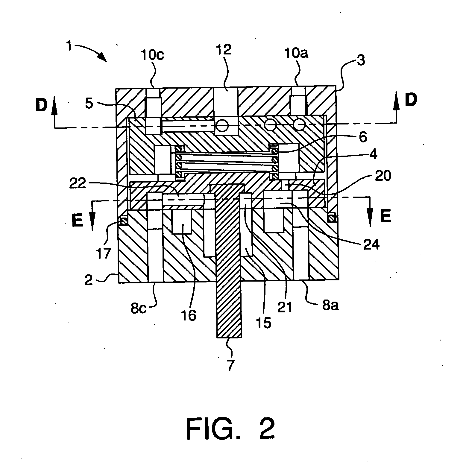
[0079] The embodiments of the present invention address the operation of pressure swing adsorption (PSA) systems that utilize rotary valves and operate using cycles in which the lowest adsorber bed pressures are below atmospheric pressure. These cycles, are commonly referred to as vacuum swing adsorption (VSA) cycles and are utilized in VSA systems. The embodiments of the invention provide improved rotary valve designs that prevent contamination of the adsorbent by components in the atmosphere surrounding the rotary valve and the VSA system. The prior art for rotary valve PSA systems discloses methods of preventing valve leakage that causes product contamination, but does not consider the problem of adsorbent contamination addressed by the embodiments of the present invention for VSA systems.

[0080] A rotary valve is a valve with one or more stators, one or more rotors rotating within the valve in sealable sliding rotary motion with the stator(s), and multiple ports in the rotor(s) ...


PUM


Abstract

Rotary valve comprising (a) a rotor having a rotor face rotatable about an axis perpendicular to the rotor face, a plurality of openings, and at least one passage connecting at least one pair of the plurality of openings; (b) a stator having a stator face in sealing contact with the rotor face to form a planar rotary valve seal with an outer periphery, a plurality of openings in the stator face that are connected to respective passages through the stator, and wherein at least one of the passages through the stator is a stator vacuum passage directly connected to a vacuum pump; (c) a sealed valve chamber having an interior volume contiguous with the outer periphery of the rotary valve seal, which chamber is sealed from the atmosphere surrounding the rotary valve; and (d) a vacuum vent passage connected to the sealed valve chamber.

Description

BACKGROUND OF THE INVENTION [0001] Rotary valves are widely used in the process industries for directing fluids from one or more process sources to one or more process destinations in repeatable cyclic process steps. These valves, also called rotary sequencing valves, are used in cyclic or repeatable processes such as gas separation by pressure or temperature swing adsorption, liquid separation by concentration swing adsorption, gas or liquid chromatography, regenerative catalytic processes, pneumatic or hydraulic sequential control systems, and other cyclic processes. A widely-used type of rotary valve has a planar circular configuration in which a flat ported rotor rotates coaxially on a flat ported stator such that ports in the stator and rotor are aligned or blocked in a predetermined cyclic sequence. Sealing typically is provided by direct contact of the flat rotor face sliding over the flat stator face. A high degree of precision is required in the fabrication of these flat su...

Claims


Application Information

Patent Timeline
IPC IPC(8): F16K11/074
CPCB01D53/0446B01D53/0454F16K11/074B01D2259/40005B01D53/0476Y10T137/5762Y10T137/86863Y10T137/86533
Inventor WAGNER, GLENN PAUL
Owner AIR PROD & CHEM INC
Learn More