All optical extended "depth-of field" imaging system

an imaging system and extended field technology, applied in the field of optical imaging systems, can solve the problems of inability to achieve the possibility of any known conventional optical system, severe misfocus, etc., and achieve the effect of wide tolerance for focusing error and significant additional weigh

Inactive Publication Date: 2007-01-02
RAMOT AT TEL AVIV UNIV LTD
View PDF4 Cites 46 Cited by
  • Summary
  • Abstract
  • Description
  • Claims
  • Application Information

AI Technical Summary

Benefits of technology

[0023]The present invention successfully addresses the shortcomings of the presently known imaging systems by providing an economical and quiet imaging system with a wide tolerance for focusing error, without significant additional weight or the need for an additional source of power.

Problems solved by technology

The image is acquired in real time without the need for a post processing stage, even in cases that, in prior-art all-optical systems, would result in severe misfocus.
This possibility cannot be achieved with any known conventional optical system.

Method used


Image

  • All optical extended "depth-of field" imaging system
  • All optical extended "depth-of field" imaging system
  • All optical extended "depth-of field" imaging system

Examples


Embodiment Construction

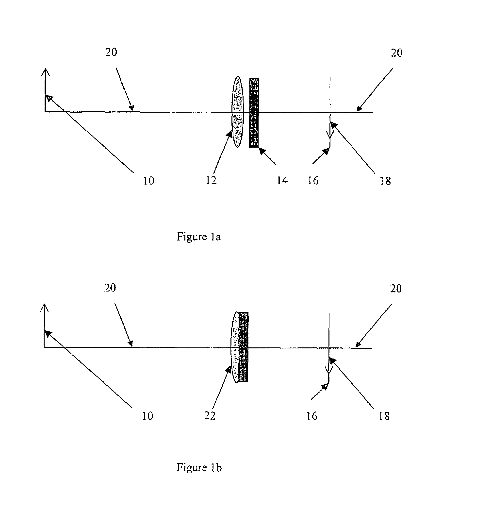
[0036]The present invention is of an optical imaging system that produces images of acceptable quality of objects located at a wide variety of distances from the optical imaging system. The present invention also reduces the sensitivity of image quality to the distance from the optical imaging system to the detector.

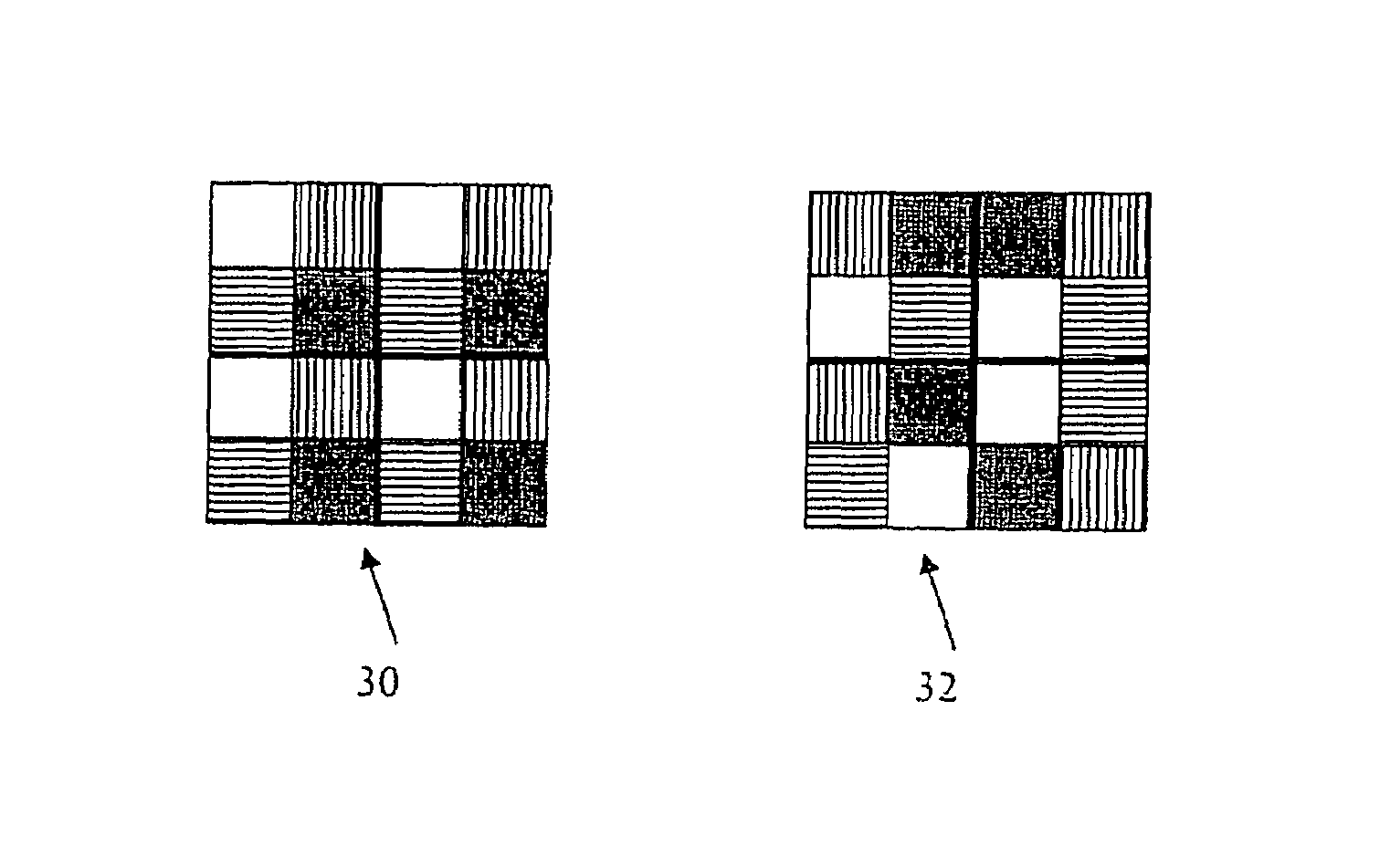
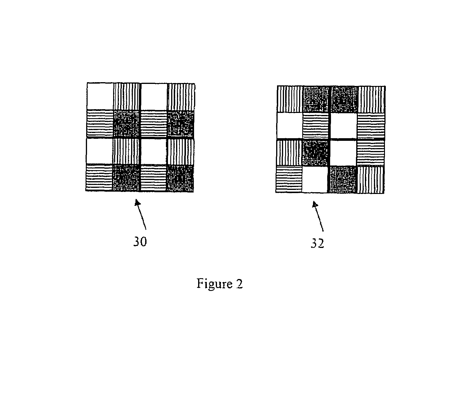
[0037]Specifically, the present invention can be used to produce images of acceptable quality for a wide range of distances from the object to the optical imaging system, and with reduced sensitivity to the distance from the optical imaging system to the detector by the use of a diffractive optical element (DOE) mask, that may include, inter alia, a multiplexed set of Fresnel lenses in conjunction with a lens, or else it may integrate the lens, too, into its structure. Such an element may be fabricated by etching a pattern into a substrate with the use of several masks, in sequence, as is commonly done in the fabrication of DOE's. Once an element, or a complementary or n...


PUM


Abstract

The instant invention is an optical imaging system that produces images of acceptable quality of objects which are located at a wide variety of distances from the optical imaging system. A preferred embodiment of the optical imaging system includes an object (10), an auxiliary lens (12), a composite phase marsk (14) and a detector (18) arranged along an optical axis (20). Light from the object (10) is focused by the auxiliary lens (12) in tandem with the composite phase mark (14), producing an image (16) which is incident th detector (18).

Description

FIELD AND BACKGROUND OF THE INVENTION[0001]The present invention relates to an optical imaging system, and, more particularly, to an all-optical extended focus imaging system including a multiplexed set of Fresnel lenses (FL's), such that the optical imaging system of the present invention produces clear images of objects at a variety of distances from the optical imaging system without requiring mechanical refocusing, although with a sacrifice of contrast and resolution when compared with an image produced by a sharply focused lens or lens system of similar size. Similarly, the present invention reduces the sensitivity of image quality to the distance of the detector from the optical imaging system.[0002]Various attempts have been made to provide optical imaging systems which can produce sufficiently sharp and bright images of objects whose distances from the optical imaging system are variable, or in situations where the distance from the optical imaging system to the detector may...

Claims


Application Information

Patent Timeline
Patent Type & Authority Patents(United States)
IPC IPC(8): G02B9/00G02B9/08G02B3/08G02B5/18G02B13/00G02B27/00
CPCG02B3/08G02B5/1871G02B27/0075G02B5/1885G02B13/00G02B5/1876
Inventor BEN-ELIEZER, EYALZALEVSKY, ZEEVMARON, EMANUELKONFORTI, NAIMMENDLOVIC, DAVID
Owner RAMOT AT TEL AVIV UNIV LTD
Why Eureka
Try Eureka