
Two piston, concentric cylinder, alpha free piston Stirling machine

a free-piston, stirling machine technology, applied in the direction of stirling type engines, machines/engines, hot gas positive displacement engine plants, etc., can solve the problems of inability to house the multiple cylinders of the alpha machine in a single casing, the 180° degree phasing of the pistons is thermodynamically inoperable, and the two-piston alpha stirling machine has not been possible before, so as to achieve efficient operation.

Inactive Publication Date: 2014-10-14
SUNPOWER
View PDF1 Cites 7 Cited by
  • Summary
  • Abstract
  • Description
  • Claims
  • Application Information

AI Technical Summary

Benefits of technology

The design achieves thermodynamically efficient operation with reduced manufacturing costs by allowing wider tolerances and enabling phase tuning, comparable to beta Stirling machines but with simpler, less costly construction.

Problems solved by technology

However, 180° degree phasing of the pistons is thermodynamically inoperable.
However, the alpha configuration has multiple cylinders and it is impractical to house the multiple cylinders of an alpha machine in a single casing.
Additionally, so far as known, a free piston, two piston alpha Stirling machine has not previously been possible.
Unfortunately, the beta configuration also has critical, small tolerance alignment and concentricity requirements in order to avoid problems of sealing the displacer's connecting rod to the piston, and rubbing of the displacer piston on the walls of its cylinder.
Meeting these requirements and avoiding the problems requires higher precision machining which translates into higher costs of manufacture.
The beta configuration ordinarily requires a relatively stiff spring for efficient operation but such a spring adds cost and a significant risk of failure from fatigue.

Method used


Image

  • Two piston, concentric cylinder, alpha free piston Stirling machine
  • Two piston, concentric cylinder, alpha free piston Stirling machine
  • Two piston, concentric cylinder, alpha free piston Stirling machine

Examples


Embodiment Construction

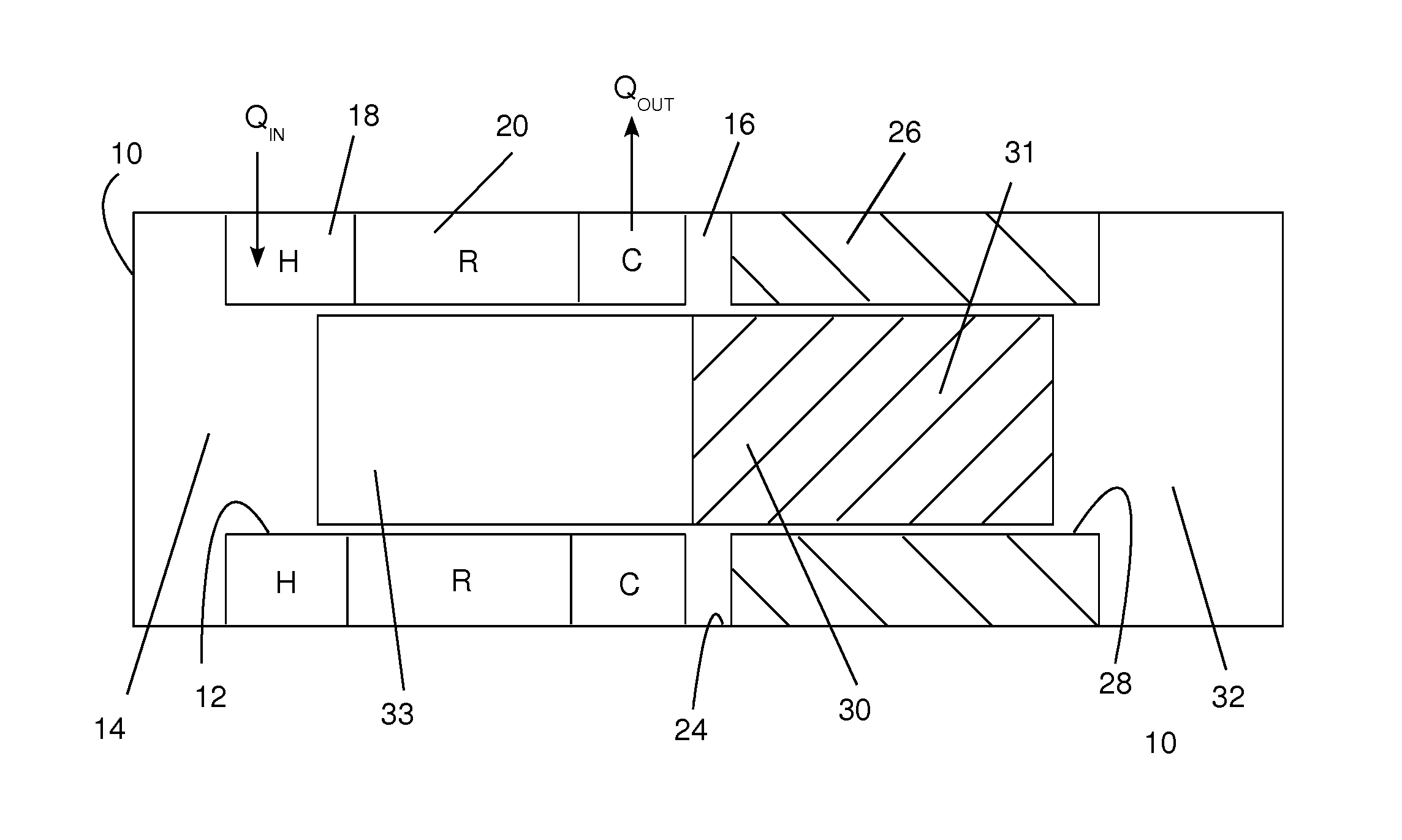
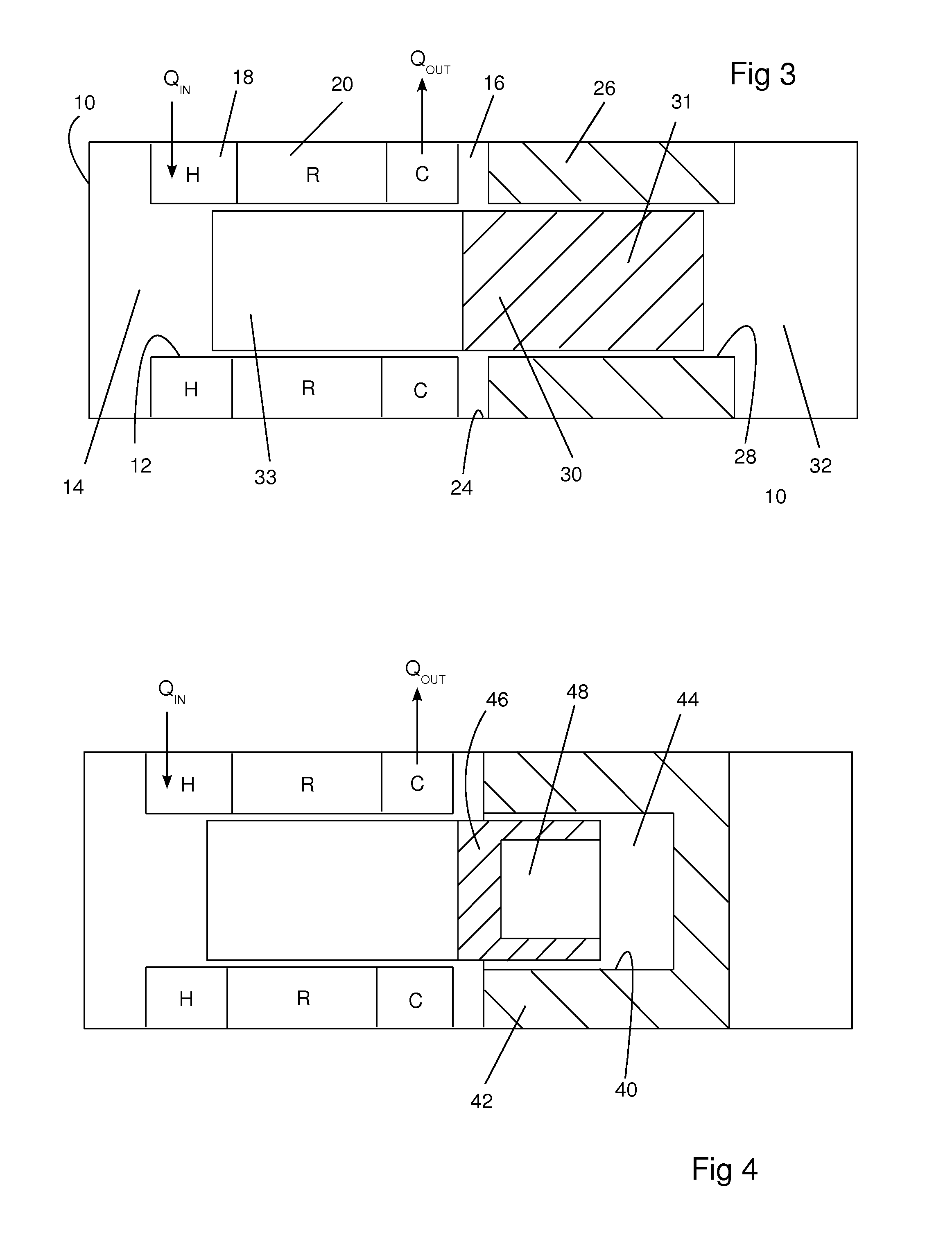
[0034]The figures are simplified diagrammatic views in order to illustrate the principles of the invention. Component parts are shown symbolically or schematically in the manner common in the art. Piston clearances are exaggerated in order to distinguish the closely fitting components. In several of the views the connection of the pistons to a prime mover or load are not illustrated because many such connections are known in the art and may be used with embodiments of the invention.

[0035]FIG. 3 illustrates a free piston, alpha, two piston, concentric cylinder, Stirling cycle machine having a casing 10 confining a working gas. A first cylinder 12 (which may also be called the expansion cylinder) has an expansion space 14 that opens into one end of the first cylinder 12 and a compression space 16 at the opposite end of the first cylinder 12. The first cylinder 12 is surrounded, in a manner that is well known in the free piston Stirling machine art, by an expansion space heat exchanger...


PUM


Abstract

A two piston, free piston, alpha Stirling cycle machine has a compression piston with a cylindrical bore that is coaxial with the cylinders in which the pistons reciprocate. An expansion piston sealingly extends into both an expansion cylinder and into the cylindrical bore in the compression piston. The expansion piston has the same diameter within both the expansion cylinder and the cylindrical bore. A spring, preferably a gas spring, drivingly connects the pistons. The reciprocation of the expansion piston varies only the volume of the expansion space and the reciprocation of the compression piston varies only the volume of the compression space. The spring that drivingly connects the pistons allows the two pistons to be properly phased without a mechanical linkage so that they can operate in a thermodynamically effective phase over a range of strokes.

Description

CROSS-REFERENCES TO RELATED APPLICATIONS[0001]This application claims the benefit of U.S. Provisional Application Nos. 61 / 586250filed Jan. 13, 2012 and 61 / 609,433 filed Mar. 12, 2012.STATEMENT REGARDING FEDERALLY-SPONSORED RESEARCH AND DEVELOPMENT[0002](Not Applicable)REFERENCE TO AN APPENDIX[0003](Not Applicable)BACKGROUND OF THE INVENTION[0004]This invention relates generally to free piston Stirling cycle engines, heat pumps and coolers and more particularly relates to a free piston alpha type of Stirling machine that, although it has two pistons, is configured so that it can be operated with a phase angle between the pistons that provides thermodynamically efficient operation without a mechanical drive linkage between the two pistons. The principal advantage of the invention is that it can be manufactured at a substantially reduced cost because it allows wider concentricity and alignment tolerances than physically comparable Stirling machines.[0005]As well known in the art, in a ...

Claims


Application Information

Patent Timeline
Patent Type & Authority Patents(United States)
IPC IPC(8): F02G1/04
CPCF02G1/0435F02G2243/206F02G2243/24
Inventor BEALE, WILLIAM T.
Owner SUNPOWER
Learn More