Method of manufacturing a modular corner assembly

a manufacturing method and corner assembly technology, applied in the direction of manufacturing tools, transportation and packaging, bearing unit rigid support, etc., to achieve the effect of eliminating tolerances and reducing the end play of the rotor

Inactive Publication Date: 2007-01-09
ROBERT BOSCH CORP
View PDF16 Cites 19 Cited by
  • Summary
  • Abstract
  • Description
  • Claims
  • Application Information

AI Technical Summary

Benefits of technology

[0026]It is a further object to this invention to provide a corner assembly for a vehicle wherein end play for a rotor is reduced by machining braking surfaces on a rotor while clamping on a knuckle to eliminate tolerances associated during the assembly of the individual components.

Problems solved by technology

Unfortunately, while the individual manufacturing tolerance of the various components that make up a corner assembly may be within desired limits when the tolerances are combined or added together a relationship may occur wherein a hub mounting surface on the wheel hub for the rotor and / or braking surface on the rotor are not in perpendicular alignment with the axis of the wheel bearing.

Method used


Image

  • Method of manufacturing a modular corner assembly
  • Method of manufacturing a modular corner assembly
  • Method of manufacturing a modular corner assembly

Examples


Embodiment Construction

[0057]In the various embodiments for a module corner assembly, same components are identified by a same number and only when structural components are different is a new number assigned even though they may function in a similar manner.

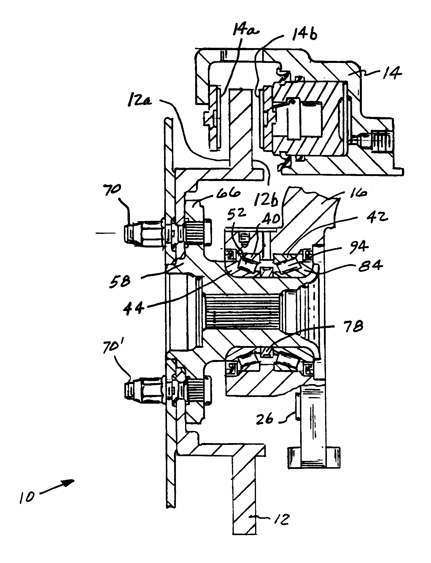
[0058]A module corner assembly 10 of the present invention is illustrated in FIG. 22 and is manufactured through a succession of steps illustrated in FIGS. 1–21. The corner assembly 10 is distinguished in that braking surfaces located on a rotor 12 are located in parallel alignment with wear faces on friction members that are retained in a caliper 14 that spans the rotor 12. The parallel alignment enhances the uniform engagement of the wear surfaces and braking surfaces while reducing surging during rotation of the rotor 12 and as a result a reduction in rotation is essentially a linear function.

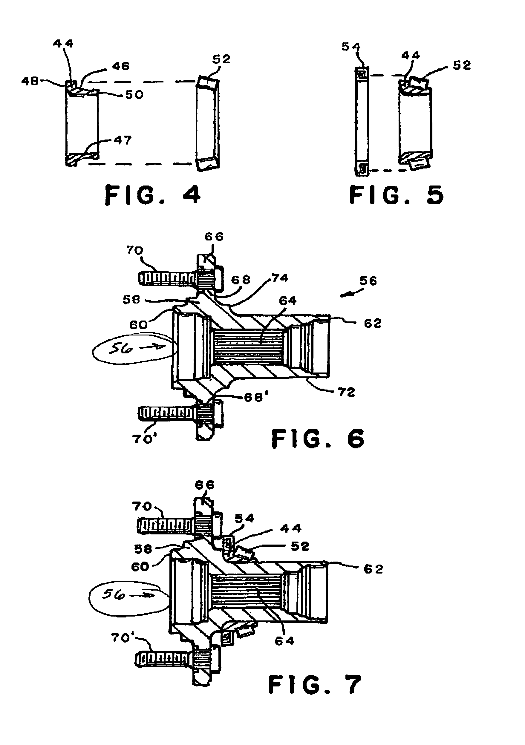
[0059]A preferred method of manufacturing the module corner assembly 10 may be achieved through the following sequentially steps.

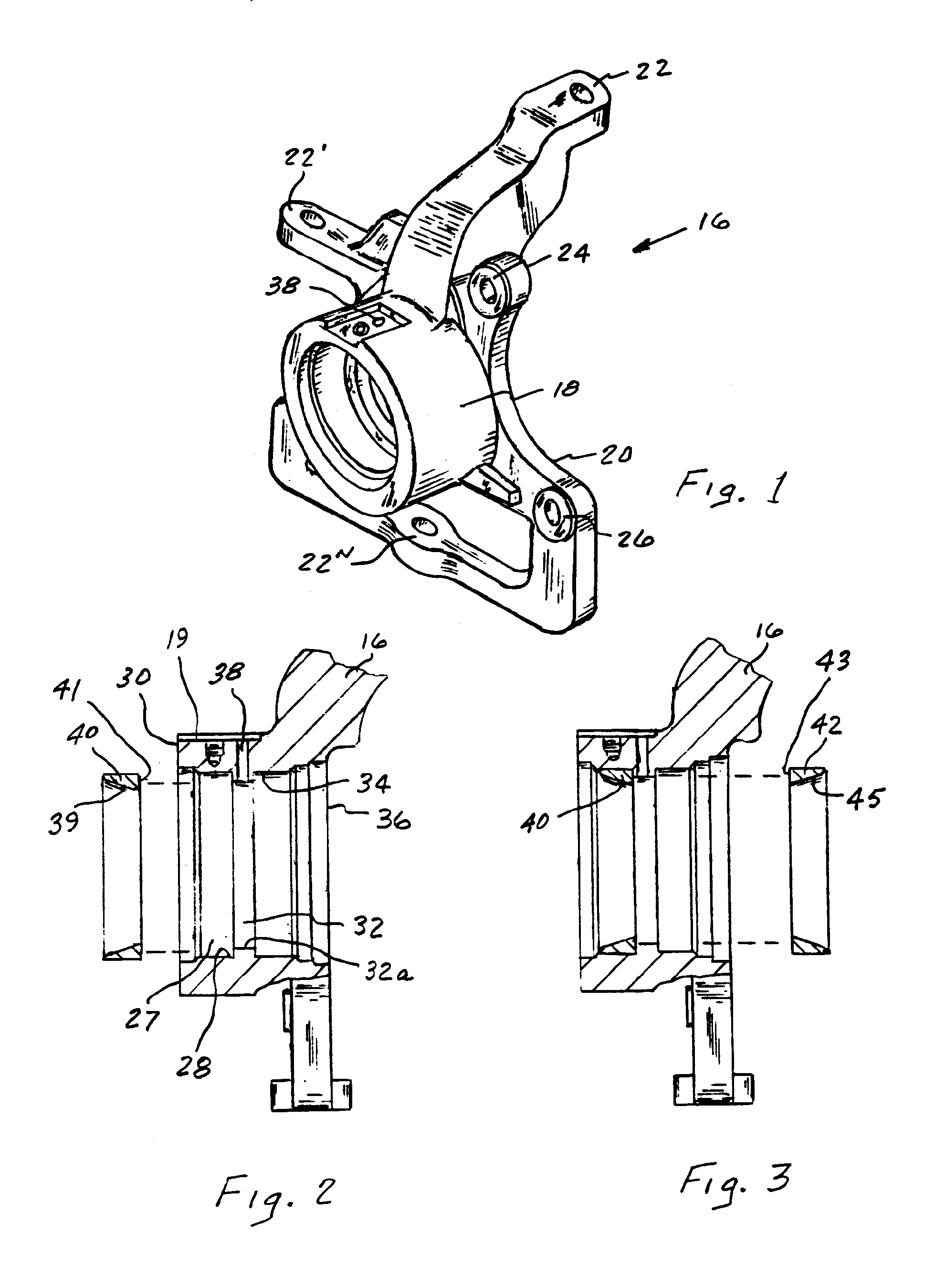
[0060]A knuckle 16 as shown i...


PUM

PropertyMeasurementUnit
distanceaaaaaaaaaa
linear distanceaaaaaaaaaa
radial distanceaaaaaaaaaa

Abstract

A module corner assembly wherein a wheel hub is permanently attached to a knuckle and various surfaces on the wheel hub and knuckle are machined in a same fixture utilized in holding the knuckle to deform an end on the wheel hub against a cone of a bearing. When a rotor is thereafter attached to the wheel hub it is also machined in the same fixture such that a perpendicular relationship is established between the axis of the wheel bearing and braking surfaces on the rotor and as a result a desired lateral run out relationship is achieved between the axis of the bearing and rotor surfaces.

Description

[0001]This invention relates to a process of manufacturing a module corner assembly having wheel hub permanently attached to a knuckle to define a unitary structure.BACKGROUND OF THE INVENTION[0002]Disc brake systems are commonly used on the front axle of most vehicles because of efficiency in stopping a vehicle. In such systems, a bearing assembly is fixed to a wheel hub that is bolted to a knuckle member, a brake rotor is thereafter attached to the wheel hub and a caliper is bolted to the knuckle member spans the rotor. The knuckle member is pivotally attached to the frame of the vehicle and a caliper is bolted to the knuckle to locate the first and second friction members on opposite sides of the rotor to define a corner assembly. During braking the friction members are moved into engagement with corresponding braking surfaces on the rotor to effect a brake application. Unfortunately, while the individual manufacturing tolerance of the various components that make up a corner ass...

Claims


Application Information

Patent Timeline
Patent Type & Authority Patents(United States)
IPC IPC(8): B62D7/18B21D53/10B21K1/04B21K1/40B23P11/00B23P17/00F16C32/00
CPCB23B5/02B60B27/0084F16C19/54F16C35/063B60B27/00Y10T29/49998F16C2326/02Y10T29/49995Y10T29/49771Y10T29/4984Y10T29/49915Y10T29/4992Y10T29/497Y10T82/10Y10T29/49689Y10T29/49536Y10T29/49682Y10T29/49684Y10T29/49535Y10T29/4978Y10T29/49696F16C43/04F16C19/543
Inventor SADANOWICZ, DAVID THOMASBRACKMANN, LARRY WILLIAMWARD, DON PAUL
Owner ROBERT BOSCH CORP
Why Eureka
Try Eureka