Rotary packaging machines

Active Publication Date: 2007-01-09
TNA AUSTRALIA
View PDF33 Cites 30 Cited by
  • Summary
  • Abstract
  • Description
  • Claims
  • Application Information

AI Technical Summary

Benefits of technology

[0011]an assembly to at least substantially prevent product being located between the jaws during sealing engagement with the tubular bag material, the assembly having a first operative configuration allowing product to pass along the bag material and a second operative configuration, the assembly when in the second configuration being engaged with the bag material to at least substantially prevent product being located between the jaws during sealing, the assembly including bag material deflecting and closing members mounted on the drive members so as to rotate therewith, which deflecting and closing members close the bag material and deflect the closed bag material laterally relative to the direction to at least substantially prevent product being located between the jaws when forming the seals.

Problems solved by technology

This can result in product above the closer bars, particularly in the case of snack foods where there are crumbs, being pulled past the closer bars.
This in turn can result in the location of product, such as crumbs, in the area between the sealing jaws.
This results in an inferior seal and frequently in the bag material being punctured.
The machines described in the above-identified patent specifications do not overcome the above-described problem.

Method used


Image

  • Rotary packaging machines
  • Rotary packaging machines
  • Rotary packaging machines

Examples


Embodiment Construction

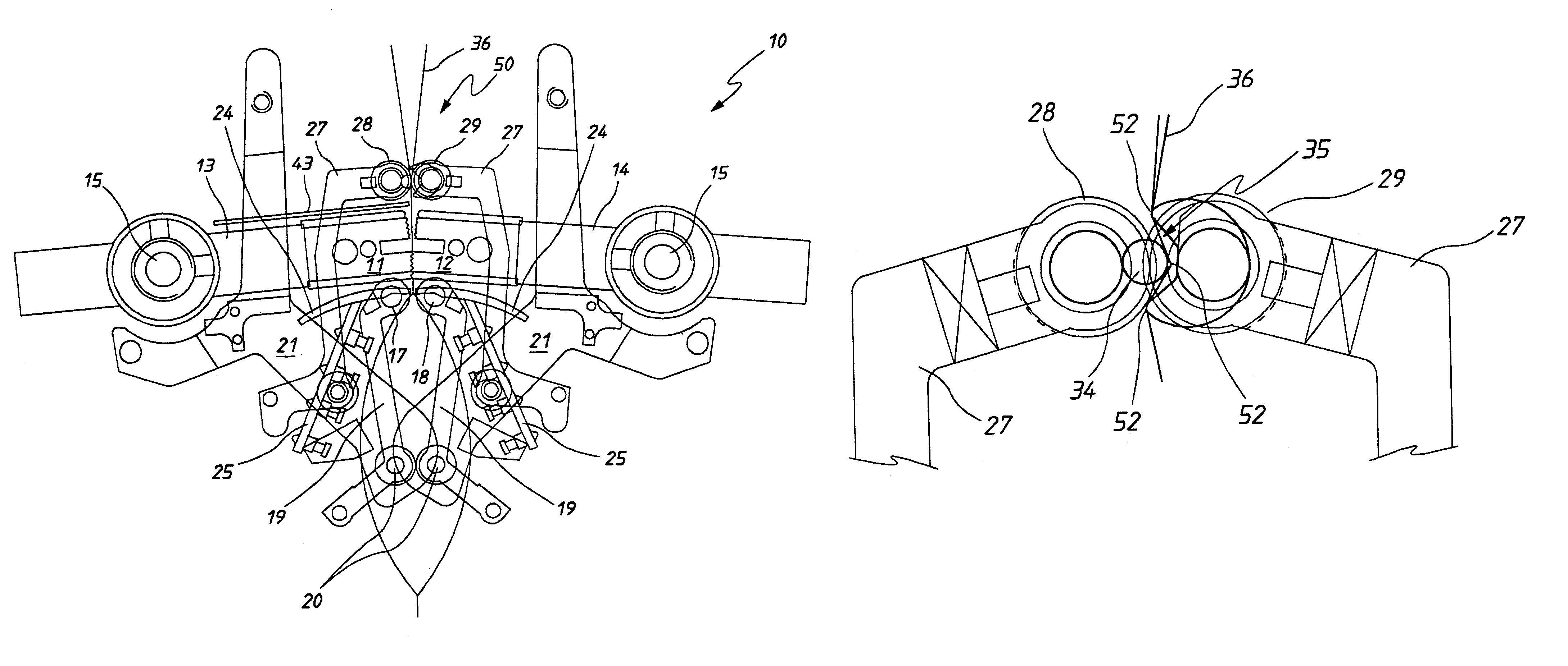
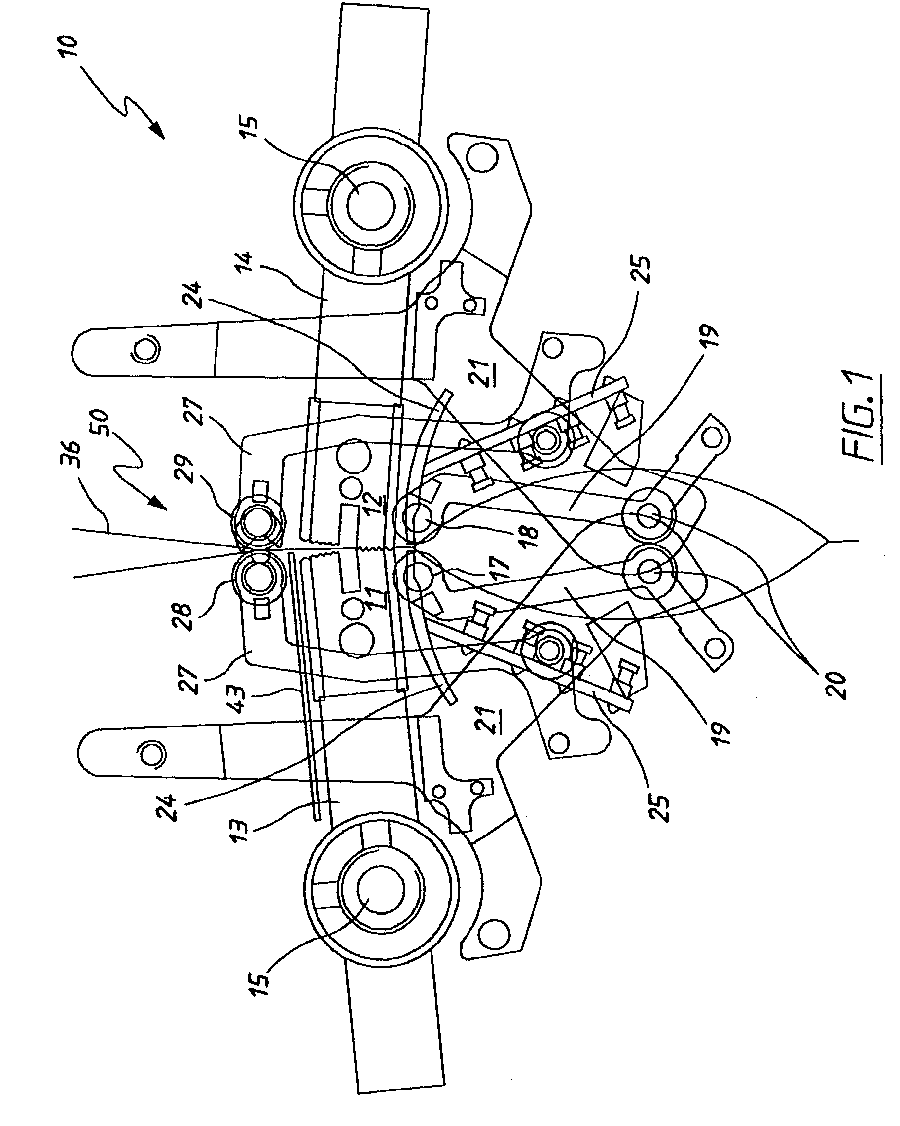
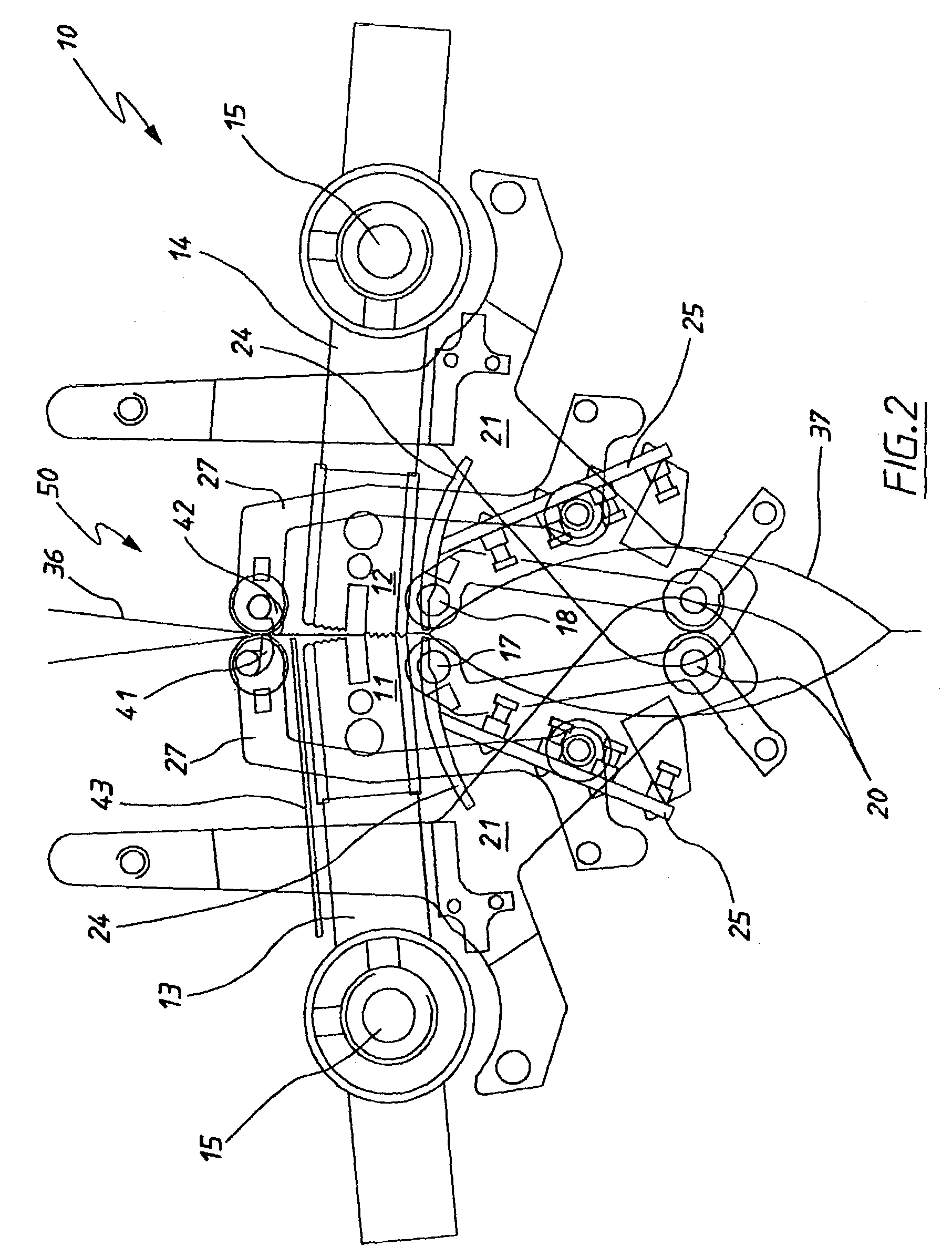
[0035]In FIGS. 1 and 5–11 of the accompanying drawings there is schematically depicted a packaging machine 10. The machine 10 is a rotary packaging machine to which there is delivered tubular bag material 36 within which product is located. The machine 10 forms transverse seals in the tubular bag material 36 and transversely cuts the tubular bag material 36 to form discrete bags 37.

[0036]The transverse seals are formed and the tubular bag material 36 cut by sealing heads 11 and 12 which are mounted on arms (driver members) 13 and 14. That is, the heads 11 and 12 have a knife blade. The arms 13 and 14 extend radially from shafts 15 and 16, which shafts 15 and 16 are rotatably driven through repeated revolutions in synchronism in opposite rotational directions about spaced parallel generally horizontal axes. The shafts 15 and 16 have generally horizontal, parallel and transversely spaced longitudinal axes. In this embodiment, the axes are substantially stationary except for movement r...


PUM


Abstract

A rotary packaging machine 10 having rotatably driven stripper bars 17 and 18 that strip tubular bag material 36 prior to sealing of the bags being formed. To further inhibit material being located between the sealing jaws there is provided tube closer bars 28 and 29. The bar 28 has a longitudinally extending projection 34 that is received within a longitudinally extending recess 35 of the bar 29. The tubular bag material 36 by engagement within the recess 35 by the projection 34 laterally projects the bag material 36 and three longitudinally spaced locations 54.

Description

TECHNICAL FIELD[0001]The present invention relates to rotary packaging machines and more particularly but not exclusively to rotary packaging machines used to package snack foods.BACKGROUND OF THE INVENTION[0002]Disclosed in U.S. Pat. No. 4,663,917 is a rotary packaging machine. The machine includes a pair of sealing jaws that are rotatably driven about parallel spaced generally horizontal axes. Associated with the jaws are stripper members which strip the bag material to inhibit product being located between the sealing jaws. Also associated with the sealing jaws are closer bars that engage the tubular bag material to again inhibit product being located between the jaws.[0003]As the sealing jaws engage the tubular bag material they are generally travelling at the same speed as the bag material. However since the jaws are corrugated the bag material upstream of the jaws is accelerated. This in turn causes the bag material to move between the closer bars to the extent that the bag ma...

Claims


Application Information

Patent Timeline
IPC IPC(8): B65B9/20B65B51/10B65B51/16B65B51/30
CPCB65B51/306
Inventor TAYLOR, ALFRED A.
Owner TNA AUSTRALIA
Why Eureka
Try Eureka