Core piece and non-contact communication type information carrier using the core piece
a technology of information carrier and core piece, which is applied in the direction of instruments, semiconductor devices, computing, etc., can solve the problems of unable to use parts feeders, unable to pack ic chips in bags or use parts feeders, and unable to have an alternative but to depend on expensive material handling, etc., to achieve good handling capability and productivity.
- Summary
- Abstract
- Description
- Claims
- Application Information
AI Technical Summary
Benefits of technology
Problems solved by technology
Method used
Image
Examples
first embodiment
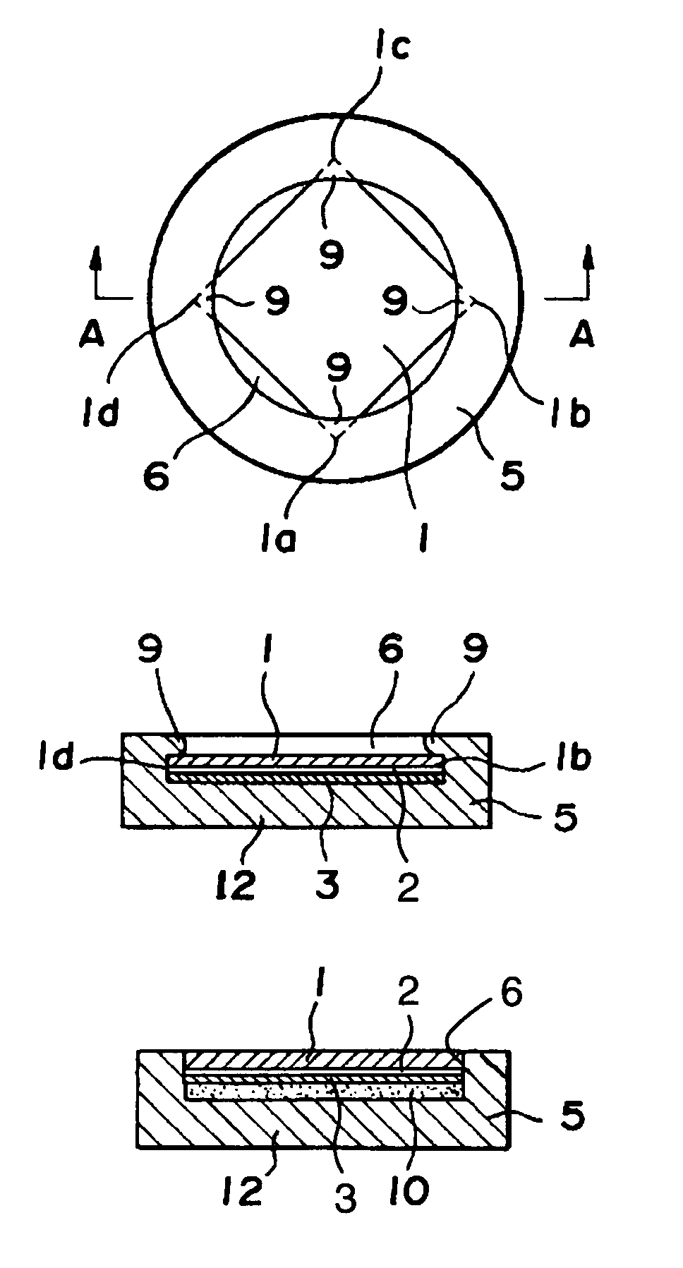
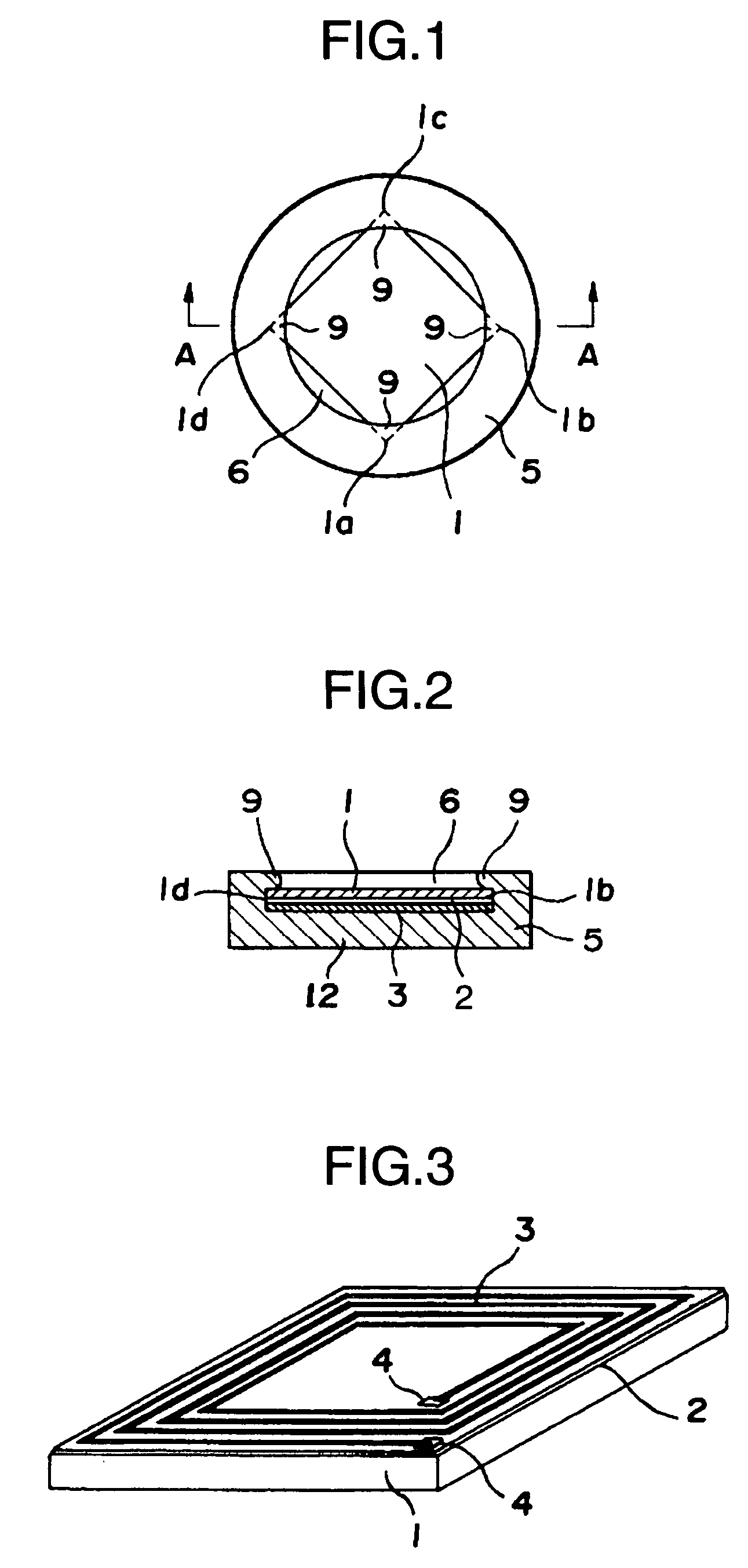
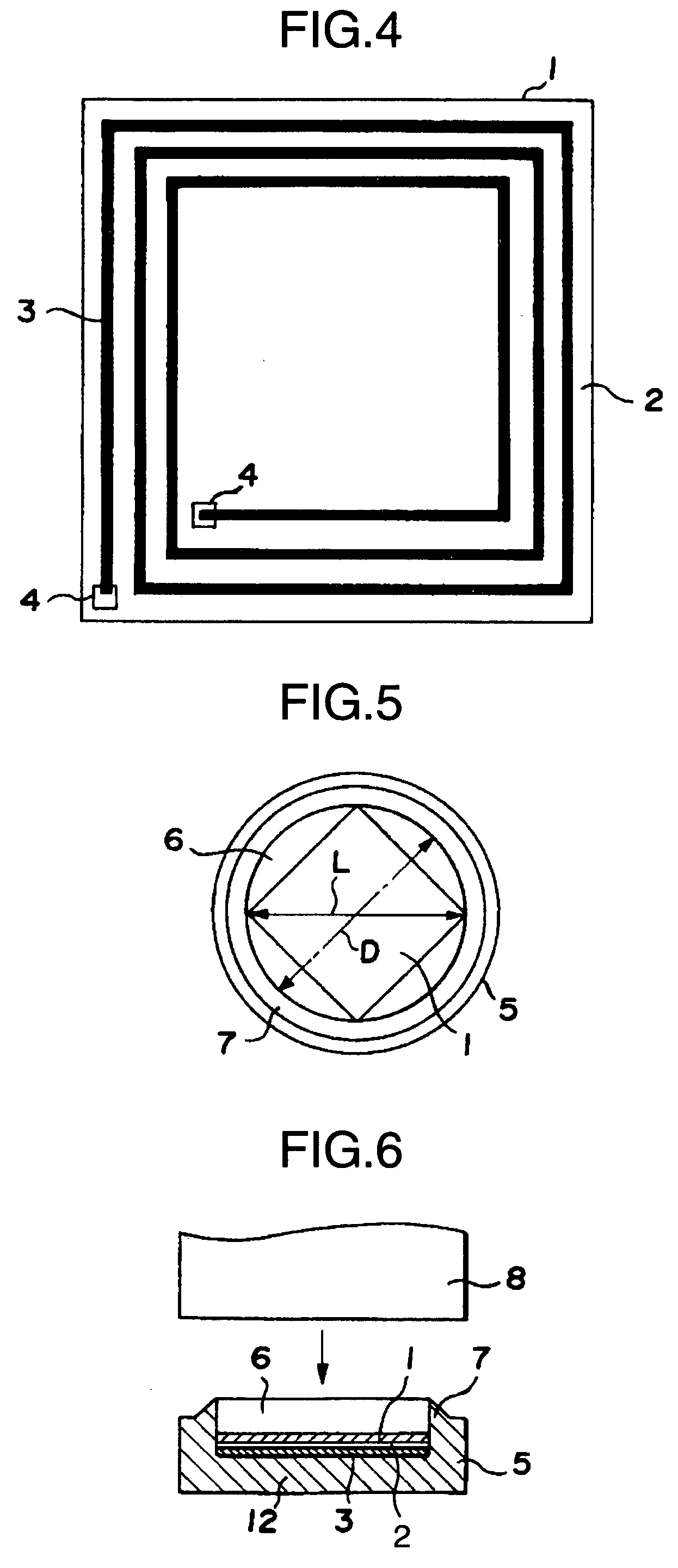
[0044]Embodiments of the present invention will be described by referring to the accompanying drawings. FIG. 1 is a plan view of a core piece for a non-contact communication type information carrier according to the FIG. 2 is a cross-sectional view taken along the line A—A of FIG. 1. FIG. 3 is an enlarged perspective view of an IC chip used in the core piece. FIG. 4 is an enlarged plan view of the IC chip. FIG. 5 and FIG. 6 are a plan view and a cross-sectional view illustrating a process of mounting the IC chip on the core piece body.
[0045]As shown in FIG. 3 and FIG. 4, a square IC chip 1 is integrally formed with a rectangular, spiral antenna coil 3 on its circuit formation side through an insulating layer 2 of, for example, polyimide resin. The antenna coil 3 can be formed by an electrocast plating method and a photoresist method and is connected at its ends to input / output terminals 4, 4 of the IC chip 1 via through-holes formed in the insulating layer 2. The IC chip 1 integral...
second embodiment
[0058]FIG. 11 to FIG. 16 illustrate the present invention. FIG. 11 represents a plan view of an IC chip, FIG. 12 an enlarged view of a portion C in FIG. 11, FIG. 13 a plan view of a core piece body, FIG. 14 a partly cutaway front view of the core piece body, FIG. 15 a plan view of a core piece, and FIG. 16 a partly cutaway front view of the core piece.
[0059]Depending on its capacity or version, the size of the IC chip 1 may become small. On the other hand, the core piece body 5 may not be able to be reduced in size because of the size of the information carrier on which the core piece body 5 is mounted. This embodiment is suitable for such a case.
[0060]The IC chip 1 used in this embodiment is square, measuring 2.3 mm on each side, and is formed integral with a spiral antenna coil 3 on a circuit formation surface through an insulating layer (not shown) of, for instance, polyimide resin. The antenna coil 3 is formed rectangular, spiraling along the outline of the IC chip 1 and, in thi...
fourth embodiment
[0071]FIG. 20 represents this invention. In this embodiment the core piece 11 is embedded in a card 43, which consists of two card halves of the same shape bonded together with the core piece 11 in between. The core piece 11 is situated at a position which is intermediate between two opposing longer sides 43a, 43b of the card 43 and which is also shifted from a center in a card insertion direction X toward the reader / writer.
[0072]FIG. 21 illustrates a fifth embodiment of this invention. A point in which this embodiment differs from the fourth embodiment is that the core piece 11 is situated at a position which is intermediate between two opposing shorter sides 43c, 43d of the card 43 and which is also shifted from a center in a card insertion direction X toward the reader / writer.
[0073]FIG. 22 illustrates a sixth embodiment of this invention. A point in which this embodiment differs from the fourth embodiment is that the core piece 11 is situated at the center of the card 43.
[0074]Th...
PUM
 Abstract
Description
Claims
Application Information
 - R&D
- Intellectual Property
- Life Sciences
- Materials
- Tech Scout
- Unparalleled Data Quality
- Higher Quality Content
- 60% Fewer Hallucinations
Browse by: Latest US Patents, China's latest patents, Technical Efficacy Thesaurus, Application Domain, Technology Topic, Popular Technical Reports.
© 2025 PatSnap. All rights reserved.Legal|Privacy policy|Modern Slavery Act Transparency Statement|Sitemap|About US| Contact US: help@patsnap.com


