Surgical table top and accessory clamp used thereon

a technology of accessory clamps and table tops, which is applied in the direction of candle holders, light support devices, building scaffolds, etc., can solve the problems of interference between the proper imaging of the patient, the inability of radiolucent materials and the inability to support the attachment of accessories

Inactive Publication Date: 2007-01-09
AMERICAN STERILIZER CO
View PDF57 Cites 53 Cited by
  • Summary
  • Abstract
  • Description
  • Claims
  • Application Information

AI Technical Summary

Benefits of technology

[0008]It is, therefore, an aspect of the present invention to provide a surgical table top capable of having an accessory clamp removably mounted thereon.

Problems solved by technology

Metal table tops or those with metal supports interfered with proper imaging of the patient.
Unfortunately, the radiolucent materials are unsuitable for supporting the attachment of accessories commonly required during medical procedures.
Even with the rails removed, however, the metal inserts interfered with the results of the imaging process.
Moreover, the metal inserts can create scatter radiation and require an increased amount of radiation and require an increased amount of radiation to be used, thereby cause potential safety problems.
Still further, since the rails extended the entire length of the table top, these rails hinder the surgeon's access to the table top.
This may cause the treating personnel to function in an awkward position increasing fatigue or interfering with access to the surgical area.
The flat clamping bar may be prone to lateral deviation because it is not restrained.
Deviation may be problematic when attempting to slide the clamp to a new position.
Since the clamping bar is unrestrained in the lateral direction, it may deviate causing the upper portion of the clamp to rub against the raised edge on the upper surface increasing the effort necessary to move the clamp or in extreme cases the clamp may bind against the edge of the table top.
This rubbing may also abrade or gouge the surfaces of the table top or its raised edge leading to further clamp-moving difficulty.
As a further disadvantage, the edges of most conventional surgical table tops are square.

Method used


Image

  • Surgical table top and accessory clamp used thereon
  • Surgical table top and accessory clamp used thereon
  • Surgical table top and accessory clamp used thereon

Examples


Embodiment Construction

[0022]In the description which follows like parts are marked throughout the specification and drawing figures with the same reference numerals, respectively. The drawing figures are not necessarily to scale and certain elements may be shown in schematic or generalized form or omitted from certain views in the interest of clarity and conciseness.

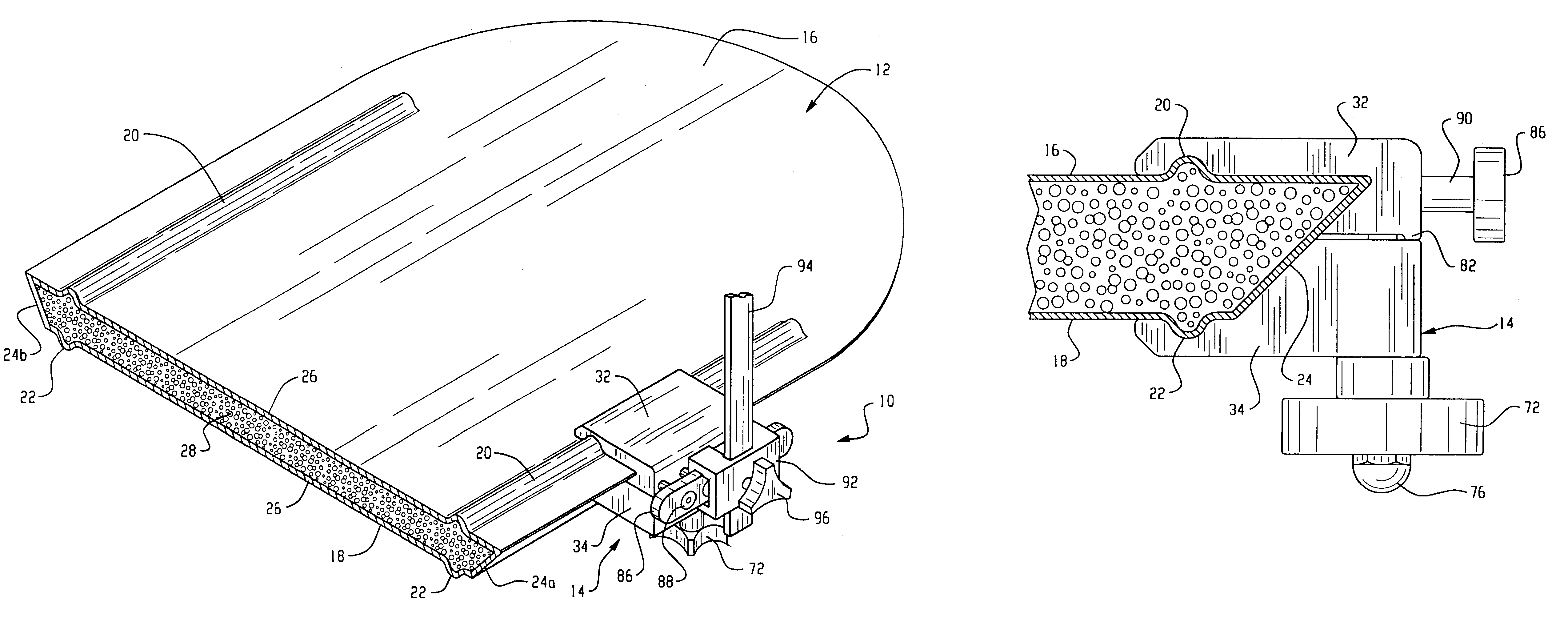
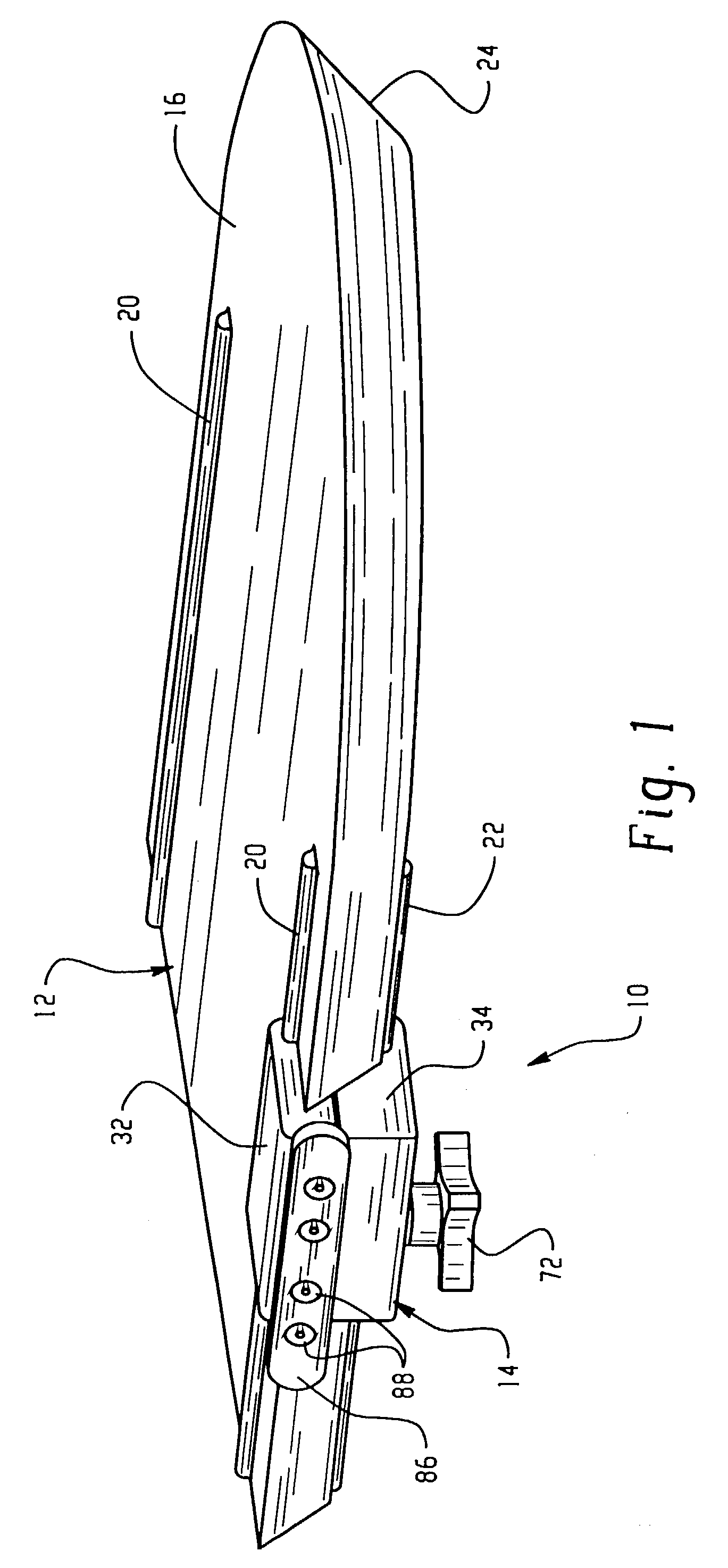
[0023]A representative medical accessory clamping system according to the concepts of the present invention is generally shown in FIGS. 1 and 5 and is generally indicated herein to by the numeral 10. This clamping system 10 generally includes a table top, referred to generally by the numeral 12, and an accessory clamp, referred to generally by the numeral 14.

[0024]Table top 12 is used to support a patient in need of care, such as for purposes of surgery or the like. It has an upper surface 16 and a lower surface 18, on which are positioned at least a set of first and second ridges, 20 and 22 near the periphery of each surface 16 and 18, respe...


PUM


Abstract

A medical accessory clamping system includes a table and an accessory clamp. The table has an upper surface and a lower surface, a first ridge positioned on the upper surface and a second ridge positioned on the lower surface of the table. The accessory clamp has a first clamping member and a second clamping member coupled to but separate from the first clamping member wherein the clamping members define a cavity for receiving a portion of the table. The first and second clamping members have recesses for receiving said first and second ridges of the table, respectively. A uniquely styled clamp and a table are also disclosed.

Description

TECHNICAL FIELD[0001]The present invention generally relates to a surgical table top and an accessory clamp for use therewith. More particularly, the present invention relates to a surgical table top having a geometric or beveled edge and at least one ridge on each of its upper and lower surfaces, and a clamp adapted to be attached to the table by receiving the geometric edge and the table's ridges.BACKGROUND OF THE INVENTION[0002]Surgical table tops have been employed to perform a variety of procedures. Oftentimes, during these procedures, the patient requires fluoroscopy or other imaging procedure. Metal table tops or those with metal supports interfered with proper imaging of the patient. To that end, surgical table tops have more recently been constructed of radiolucent materials such as, for example, carbon fiber or other composites. Such table tops lacking metal components provided a patient supporting surface that did not interfere with imaging procedures.[0003]Unfortunately,...

Claims


Application Information

Patent Timeline
Patent Type & Authority Patents(United States)
IPC IPC(8): A47G1/10A61G15/10F16M13/02
CPCA61G15/10F16M13/02F16M11/046F16M13/022Y10T24/44034Y10T24/44308Y10T24/44
Inventor EASTERLING, BARRY A.
Owner AMERICAN STERILIZER CO
Why Eureka
Try Eureka