
High speed protocol for interconnecting modular network devices

Active Publication Date: 2007-01-09
AVAGO TECH INT SALES PTE LTD
View PDF11 Cites 79 Cited by
  • Summary
  • Abstract
  • Description
  • Claims
  • Application Information

AI Technical Summary

Benefits of technology

[0009]It is an object of this invention to overcome the drawbacks of the above-described conventional network devices and methods. The present invention provides for a new protocol to act as a standard mechanism to allow for the interconnection of network devic

Problems solved by technology

Also, the header may contain an opcode that identifies whether the incoming data packet is a uni

Method used


Image

  • High speed protocol for interconnecting modular network devices
  • High speed protocol for interconnecting modular network devices
  • High speed protocol for interconnecting modular network devices

Examples


Example

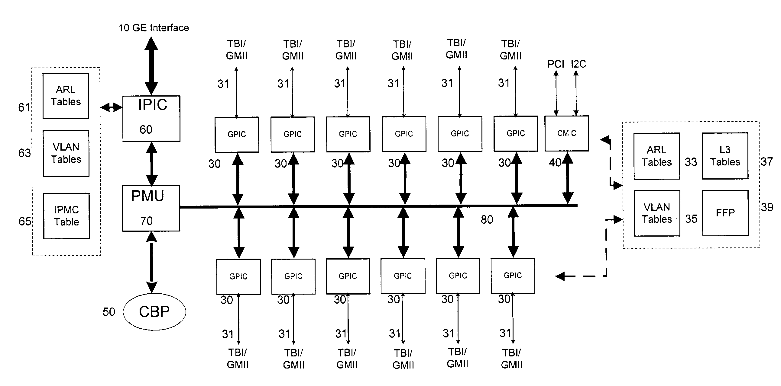
[0025]The HiGig protocol provides a standard mechanism to interconnect switches to form a single system. Such a system can be several stacked switches or a chassis system with several switch blades and fabric switch blades. The HiGig protocol enables the forwarding of packets for unicast, broadcast, layer 2 multicast, IP multicast, unknown unicast and control frames. In addition, it also allows port monitoring across multiple switches and also eternalizes packet classification information from the switch. An exemplary embodiment of a switch is discussed below to provide a framework for use of the HiGig protocol.

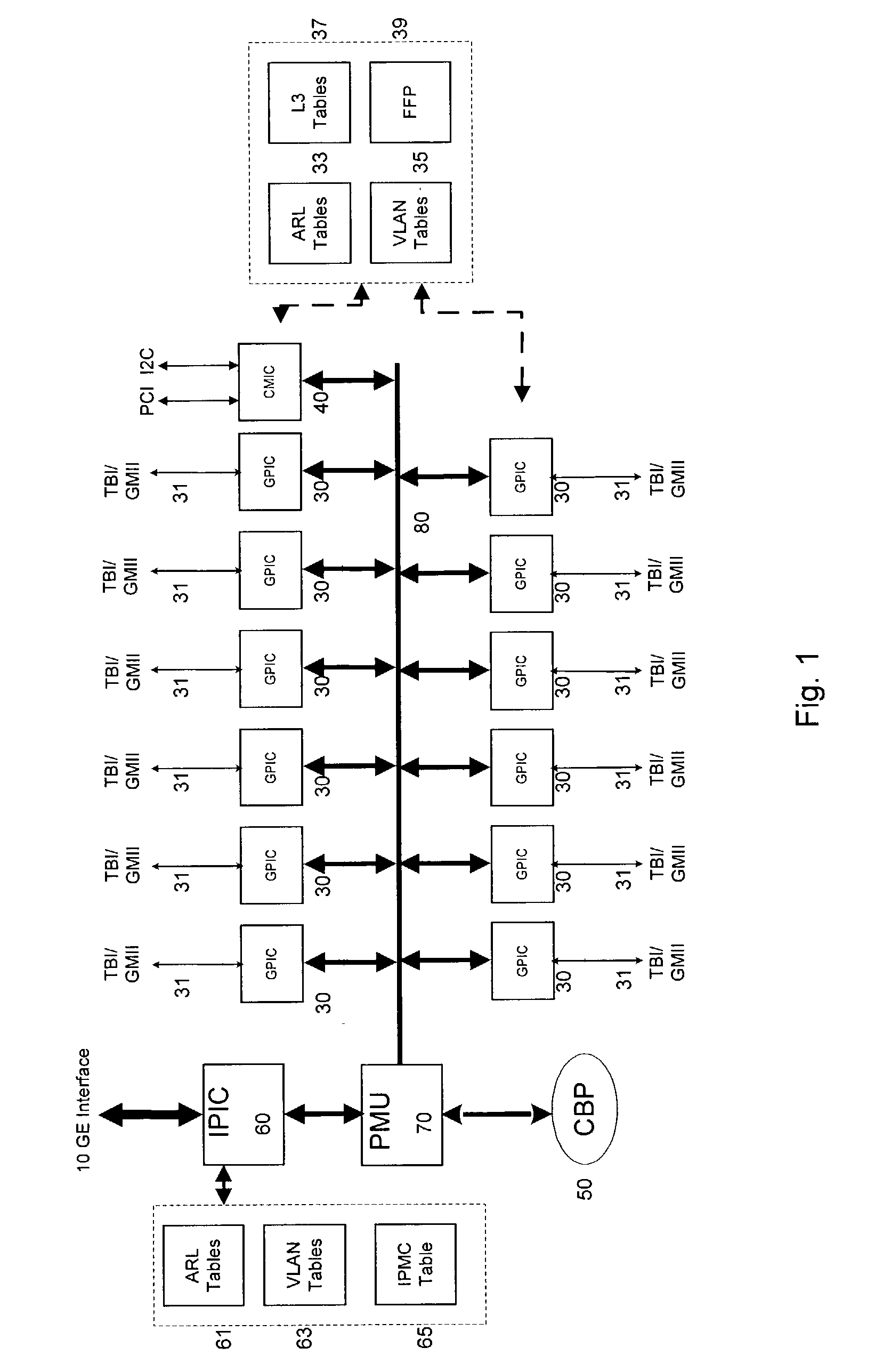
[0026]FIG. 1 illustrates a configuration wherein a switch-on-chip (SOC) 10, in accordance with the present invention, is illustrated. The following are the major blocks in the chip: Gigabit Port Interface Controller (GPIC) 30; Interconnect Port Interface Controller (IPIC) 60; CPU Management Interface Controller (CMIC) 40; Common Buffer Pool (CBP) / Common Buffer Manager (CBM) 5...


PUM


Abstract

A network switch for network communications is disclosed. The switch includes a first data port interface, supporting at least one data port transmitting and receiving data at a first data rate and a second data port interface, supporting at least one data port transmitting and receiving data at a second data rate. A memory management unit for communicating data from at least one of the first data port interface and the second data port interface and a memory is also included. The switch uses a communication channel for communicating data and messaging information between the first data port interface, the second data port interface, and the memory management unit. The switch also has a plurality of lookup tables, including an address resolution lookup table, a VLAN table and module port table. The network switch has a unique module identifier and of the first data port interface and the second data port interface is configured to determine forwarding information from a header for an incoming data packet received at a port of the one data port interface. The port interfaces are configured to determine the forwarding information from the header and to determine a destination module identifier for a destination port for the data packet from the module port table.

Description

[0001]This nonprovisional application claims the benefit of U.S. Provisional Application No. 60 / 364,135, filed Mar. 15, 2002. The contents of the provisional application are hereby incorporated by reference.BACKGROUND OF THE INVENTION[0002]1. Field of Invention[0003]The present invention relates to a method and apparatus for allowing data to be passed between interconnected network devices. More specifically, the method and apparatus allows for the use of a specific protocol to allow for this communication between network devices.[0004]2. Description of Related Art[0005]As computer performance has increased in recent years, the demands on computer networks has significantly increased; faster computer processors and higher memory capabilities need networks with high bandwidth capabilities to enable high speed transfer of significant amounts of data. The well-known Ethernet technology, which is based upon numerous IEEE Ethernet standards, is one example of computer networking technolo...

Claims


Application Information

Patent Timeline
IPC IPC(8): H04L12/28H04L12/56H04L12/50H04L12/66H04L12/413H04L12/44
CPCH04L45/48H04L49/352H04L2012/445H04L49/354
Inventor SAMPATH, SRINIVASKALKUNTE, MOHAN
Owner AVAGO TECH INT SALES PTE LTD
Learn More