Dock leveler with inflatable bag

a leveler and inflatable technology, applied in the field of levelers, can solve the problems of many high wear components, difficult operation, and high cost of purchase and service, and achieve the effect of improving the bag construction and simple design

Active Publication Date: 2007-01-16
NORDOCK
View PDF21 Cites 33 Cited by
  • Summary
  • Abstract
  • Description
  • Claims
  • Application Information

AI Technical Summary

Benefits of technology

[0009]It is another object of the invention to have an improved bag construction that is simple in design and requires only one chamber.
[0011]It is another object of the invention that the bag assembly or support pan assembly be an integral rigid part of the frame assembly and not pivot, roll or otherwise push onto a building pit floor, therefore allowing full operation in a self contained system.
[0013]It is another object of the invention that a maximum travel stop shall limit the upward movement of the ramp assembly.
[0014]It is another object of the invention that the dock leveler can be shipped without the need for the bag or pan assemblies to be tied or otherwise fastened in a raised position.
[0016]It is another object of the invention that the blower assembly be easily accessible for service or replacement without the need to remove the bag or pan assemblies.

Problems solved by technology

Hydraulic dock levelers can be efficient, but are generally more costly to purchase and service.
They are also prone to fluid leaks.
Spring powered dock levelers are often less costly, but have many high wear components and are more difficult to operate.
One problem with these designs is that they require bags with multiple sections and complex methods of construction that increases material, manufacturing and assembly cost, as well as increase friction between parts and the potential for rupture or failure.
Another problem is that other components rub against the bag during operation.
This rubbing or friction causes wear that leads to leaks in the bag or its rupture.
This friction results from the movement of the bag to accommodate the arced movement of the ramp relative to the pit floor or support pan.
Another problem with these designs is that they rely on the pit floor to form the bottom support for the bag, which requires complex installation and shipping methods, particularly to protect the bag from damage.

Method used


Image

  • Dock leveler with inflatable bag
  • Dock leveler with inflatable bag
  • Dock leveler with inflatable bag

Examples


Embodiment Construction

[0028]While this invention is susceptible of embodiment in many different forms, the drawings and photographs show and the specification describes in detail preferred embodiments of the invention. It should be understood that the drawings and specification are to be considered an exemplification of the principles of the invention. They are not intended to limit the broad aspects of the invention to the embodiments illustrated.

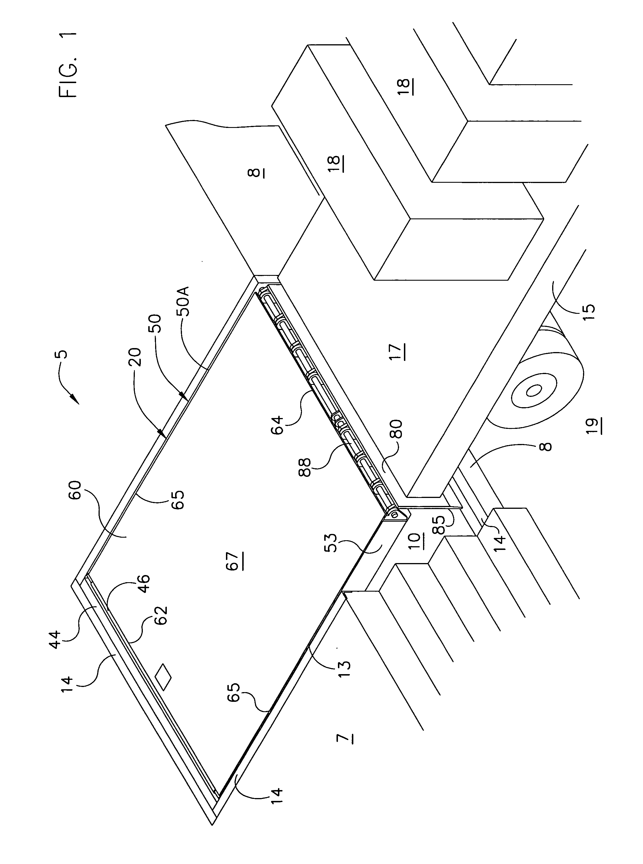
[0029]FIG. 1 shows a building or structure 4 with a loading dock 5. The loading dock 5 has a generally flat, horizontal, elevated floor surface 7 and a generally vertical front wall 8. The building 4 has a doorway 9 with an overhead door (not shown). The loading dock 5 has a pit 10 of sufficient depth to house a dock leveler. The pit 10 has a bottom floor or surface 11, a rear wall or surface 12, opposed sidewalls or surfaces 13, and an open front. The floor 11 is generally horizontal or slightly sloped for drainage, and is spaced down a desired distance from t...


PUM


Abstract

An air operated dock leveler is provided to selectively raise and lower a deck with an extendable lip. The deck includes a downwardly extending deck lift arm. An air lift assembly includes a single chamber, inflatable bag positioned between a stationary lower bag support and movable upper platform. A pull line is secured to the platform and the deck lift arm. When actuated, a blower inflates the bag and raises the platform. The pull line pulls the deck lift arm forward and raises the deck to an inclined position. When the blower is turned off, the ramp descends until the now extended lip engages the bed of a truck. After loading or unloading the trailer, the bag is reinflated to raise the ramp and retract the lip. The blower is then turned off, and the ramp descends to its stored position.

Description

TECHNICAL FIELD OF THE INVENTION[0001]This invention relates to a dock leveler with a deck lift assembly having an inflatable air bag to raise and lower the deck.BACKGROUND OF THE INVENTION[0002]Dock levelers are utilized in the transfer of goods between a building and a trailer by bridging the gap from the building floor to the trailer bed. Dock levelers include a frame or support structure for mounting the leveler in a pit of a loading dock. The rear end of a conventional dock leveler is hinged to the building floor. The opposite end has an extendable lip plate that pivots out and onto the trailer bed. Levelers are adapted to move from a generally horizontal position where the upper surface of the ramp is flush with the surface of the building floor to a second generally inclined position to provide a ramp between the bed of the truck and the dock floor.[0003]Conventional methods of lifting the dock leveler use springs, hydraulics, and more recently low pressure air. All methods a...

Claims


Application Information

Patent Timeline
Patent Type & Authority Patents(United States)
IPC IPC(8): E01D1/00
CPCB65G69/2823B65G69/2817
Inventor GLEASON, DENIS
Owner NORDOCK
Why Eureka
Try Eureka