Storage device with variable storage capacity

a storage device and variable storage technology, applied in the direction of instruments, tobacco, instruments for dispensing discrete objects, etc., can solve the problems of high manufacturing cost, difficult or completely impossible use, complicated maintenance or service of storage devices of this kind, etc., and achieve safe and reliable transportation of sensitive products, economic and technical simple storage

Inactive Publication Date: 2007-01-16
HAUNI MASCHINENBAU AG
View PDF18 Cites 11 Cited by
  • Summary
  • Abstract
  • Description
  • Claims
  • Application Information

AI Technical Summary

Benefits of technology

[0008]The present invention provides an economical and technically simple storage device which safely and reliably guarantees the transport of sensitive products.
[0009]The invention therefore provides for a device wherein the full strand and the empty strand are arranged side by side in a common horizontal plane, wherein to each layer of the full strand is allocated a corresponding layer of the empty strand in the same plane. In this way, on the one hand, a compact storage device is created which has a small overall height, as a “multi-storey” structure is avoided. The constructional size is also reduced in relation to the length of the storage device owing to the interleaved structure of the full strand and the empty strand in comparison to the known solutions, yet with the same storage capacity. The loop-type guiding of the full strand, on the one hand, and the meander-shaped guiding of the empty strand, on the other hand, enable a reduction in the dimensions of the store in a particularly efficient and simple way. On the other hand, the configuration of the storage device according to the invention also achieves an appreciable reduction in parts, which, on the one hand, lowers manufacturing costs and, on the other hand, reduces maintenance expenditure. A particular advantage of the storage device according to the invention is that the running direction of the conveying element can be freely chosen, so the multiplicity of layouts, and therefore the range of use for this storage device, is increased. By allocating one layer of the full strand and of the empty strand in one plane in each case, crossings over of the individual areas of the conveying element are additionally avoided, increasing the safety and reliability of the storage device.
[0010]In a preferred embodiment of the invention the movable plate towers of the empty strand and the movable disc tower of the full strand are arranged on a common slide and movable as a unit. Utilizing this arrangement, particularly simple and stable guiding of the plate towers and the disc tower can be guaranteed, a reduction in parts being achieved by the commonly used slide.

Problems solved by technology

On the one hand, this has the disadvantage that the known storage device has a great overall height, making it difficult or completely impossible to use, especially in factory halls with a low ceiling height.
On the other hand, maintenance or servicing of a storage device of this kind is very complicated, as individual parts are sometimes difficult to access.
Furthermore, the known storage device has a great multiplicity of parts, leading to high manufacturing costs.
This has, on the one hand, the disadvantage that the overall height of the known storage device is considerable and, indeed, is conditional on layering, either in blocks or alternately, of the individual windings of the full strand and the empty strand in the area of the common guide element.
On the other hand, the known structure requires a multiplicity of reversals or reversing devices, leading to a great multiplicity of parts.

Method used


Image

  • Storage device with variable storage capacity
  • Storage device with variable storage capacity
  • Storage device with variable storage capacity

Examples


Embodiment Construction

[0049]The particulars shown herein are by way of example and for purposes of illustrative discussion of the embodiments of the present invention only and are presented in the cause of providing what is believed to be the most useful and readily understood description of the principles and conceptual aspects of the present invention. In this regard, no attempt is made to show structural details of the present invention in more detail than is necessary for the fundamental understanding of the present invention, the description taken with the drawings making apparent to those skilled in the art how the several forms of the present invention may be embodied in practice.

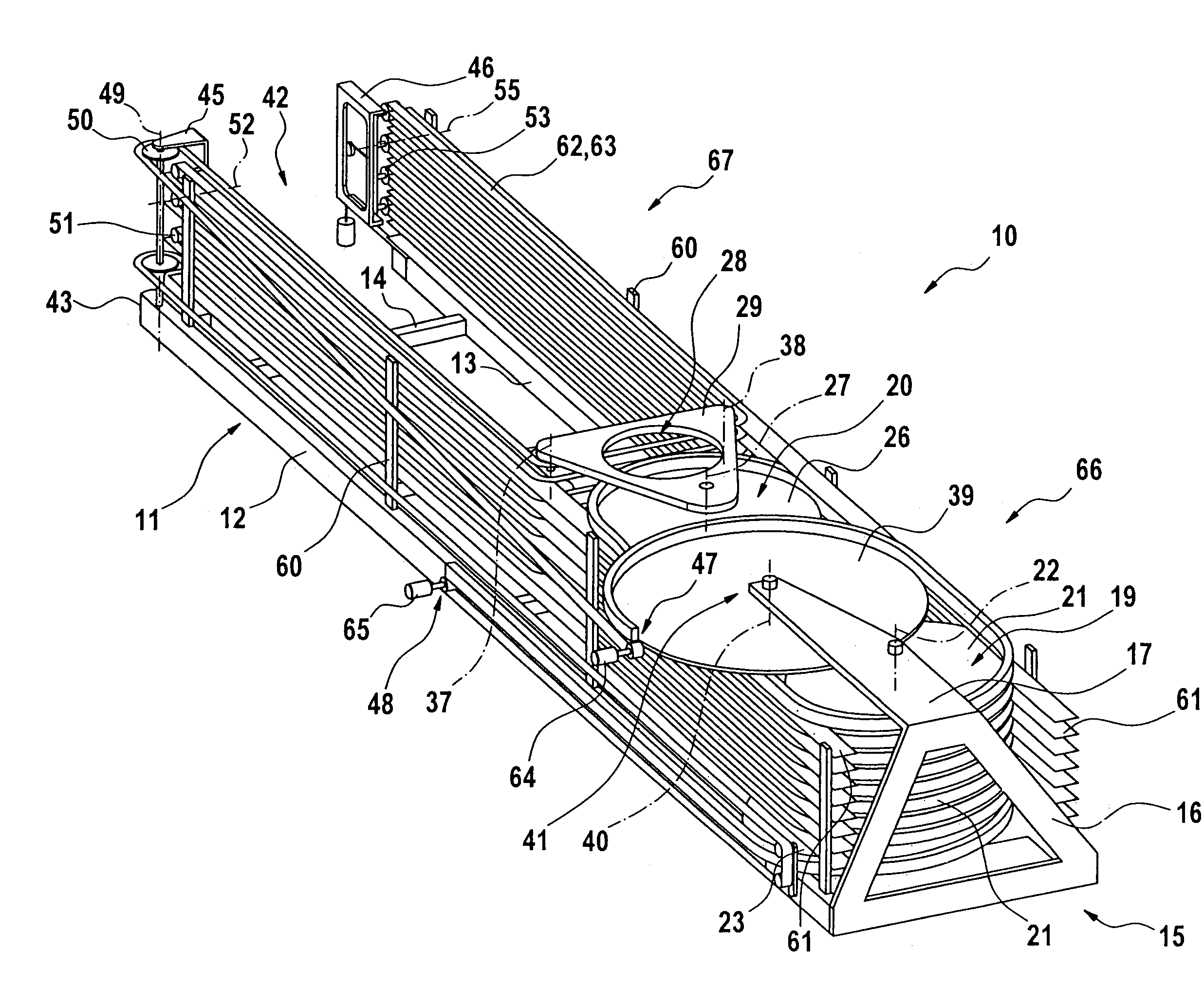
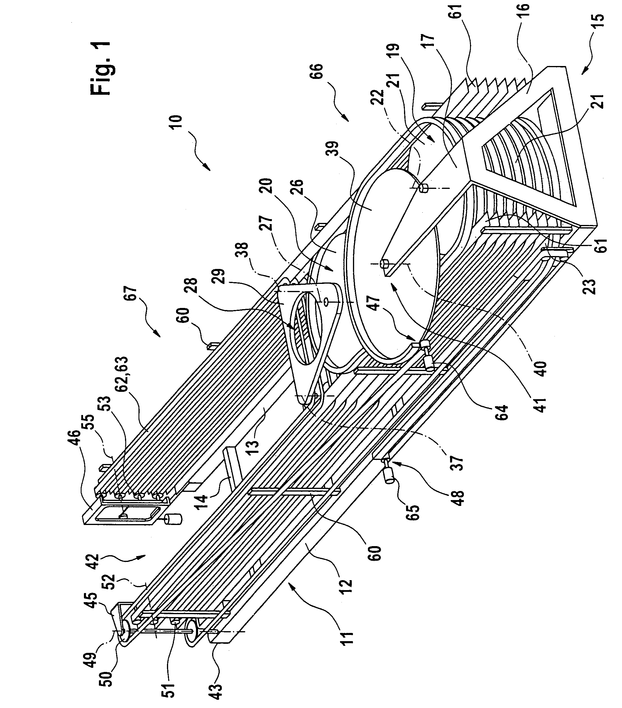
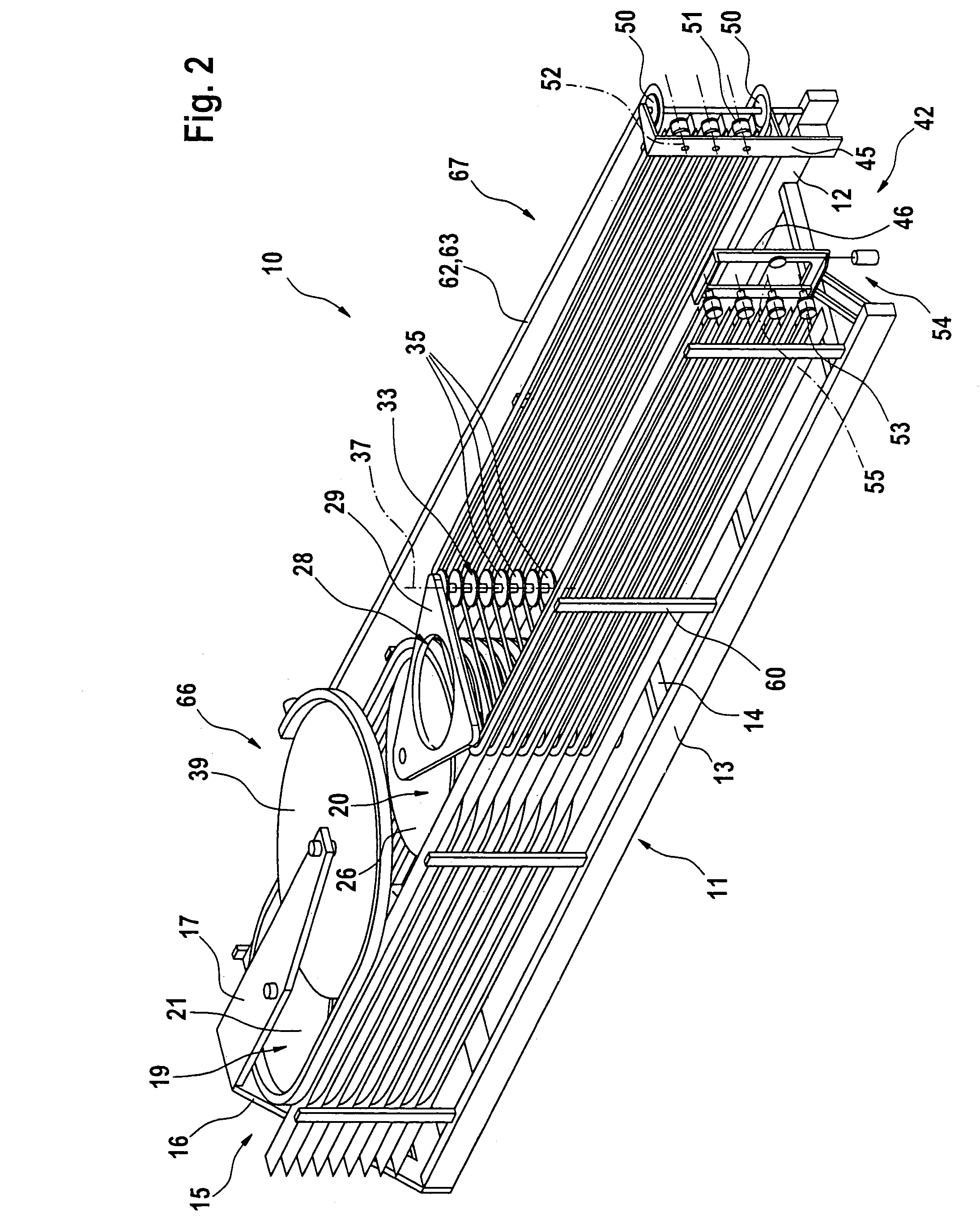
[0050]The storage device described below with reference to FIGS. 1–7 serves as linking element between a first (not illustrated) cigarette-making machine, e.g., a maker, and a second (not illustrated) cigarette-packing machine, e.g., a packer. The storage device is suitable in particular for conveying and storing cigarett...


PUM


Abstract

Storage device with variable storage capacity. The storage device includes an input area, an output area, a continuous conveying element connecting the input area to the output area. The continuous conveying element is guided by guide elements in a looping manner from the input area to the output area, whereby the continuous conveying element defines a multi-layered storage area adapted to store products and a multi-layered return area adapted to be free of products. The multi-layered storage and return areas are arranged side by side and change in length depending on a state of fullness of the storage device while an overall length of the continuous conveying element remains generally constant. At least one storage layer of the multi-layered storage area and at least one storage layer of the multi-layered return area is arranged on a common horizontal plane. This Abstract is not intended to define the invention disclosed in the specification, nor intended to limit the scope of the invention in any way.

Description

CROSS-REFERENCE TO RELATED APPLICATIONS[0001]The present application claims priority under 35 U.S.C. §119 of European Patent Application No. 03 09 0031.0, filed on Feb. 5, 2003, the disclosure of which is expressly incorporated by reference herein in its entirety.BACKGROUND OF THE INVENTION[0002]1. Field of the Invention[0003]The invention is concerned with a storage device with variable storage capacity, in particular for storing rod-shaped products, with an input area, an output area and also a continuous conveying element connecting the input area to the output area, in such a way that the storage device operates on the principle of “first in-first out” (FiFo store). The conveying element, which is guided by way of guide elements in a loop from the input area to the output area, has a multi-layered storage area, normally provided with products, namely a so-called full strand, and a multi-layered return area, normally free of products, namely a so-called empty strand. The two area...

Claims


Application Information

Patent Timeline
Patent Type & Authority Patents(United States)
IPC IPC(8): B65G1/00A24C5/35B65G47/51
CPCB65G47/5122B65G2207/24
Inventor MUELLER, THOMAS
Owner HAUNI MASCHINENBAU AG
Why Eureka
Try Eureka