Backboard 2

a backboard and board technology, applied in the field of backboards, can solve the problems of affecting the stability of the board, affecting the normal use of the board, so as to achieve the effect of providing stability to the board

Inactive Publication Date: 2007-01-16
SPINOSA JOSEPH
View PDF13 Cites 5 Cited by
  • Summary
  • Abstract
  • Description
  • Claims
  • Application Information

AI Technical Summary

Benefits of technology

[0006]The invention consists of a rectangular board and two freestanding upright support posts. The board is mounted on a bed and serves as the platform from which exercises are performed. The support posts serve to provide stability to the board and to provide a means to attach the board to the bed.
[0007]Together, the invention and bed become a trunk strengthening device. The board and the two support posts are easily assembled and disassembled and require minimal space for storage when not in use.
[0009]The addition of the first supporting post represents a departure from the previous art as detailed in reference U.S. Pat. No. 6,890,289, Spinosa, May 10, 2005. The first supporting post enables users of greater height and weight to exercise on the board while providing increased stability to both bed and board.

Problems solved by technology

The costs in terms of medical treatment, time lost from work, and disruption of normal activities are significant.
Exercise devices for trunk strengthening have been offered in the past, but they tend to be expensive and inconvenient to use at home.

Method used


Image

  • Backboard 2
  • Backboard 2
  • Backboard 2

Examples


Embodiment Construction

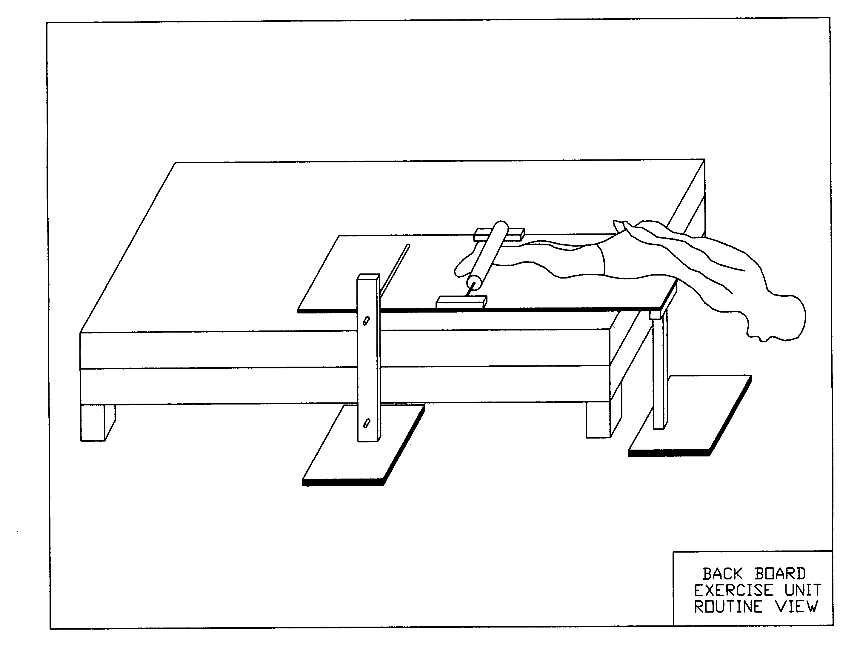
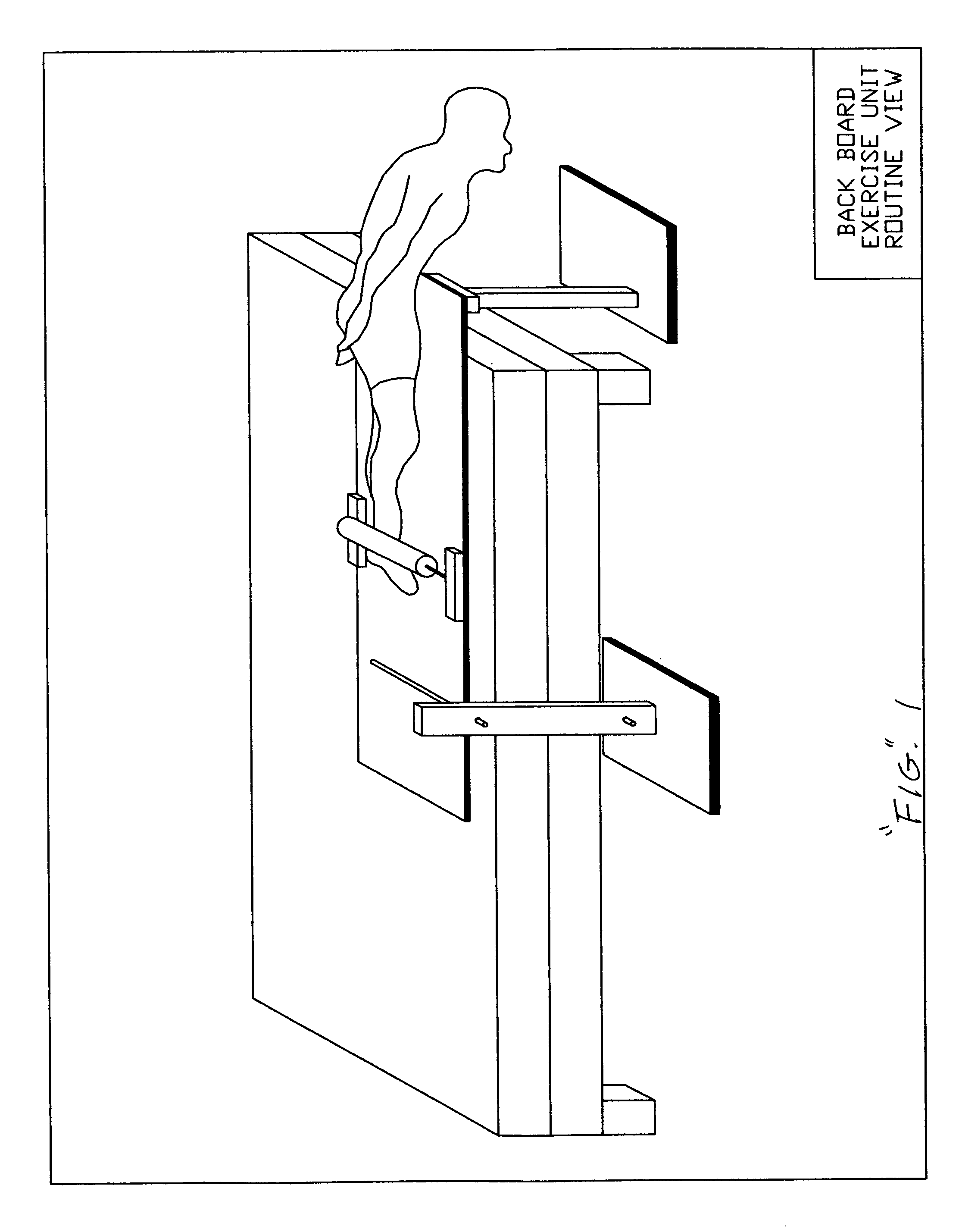
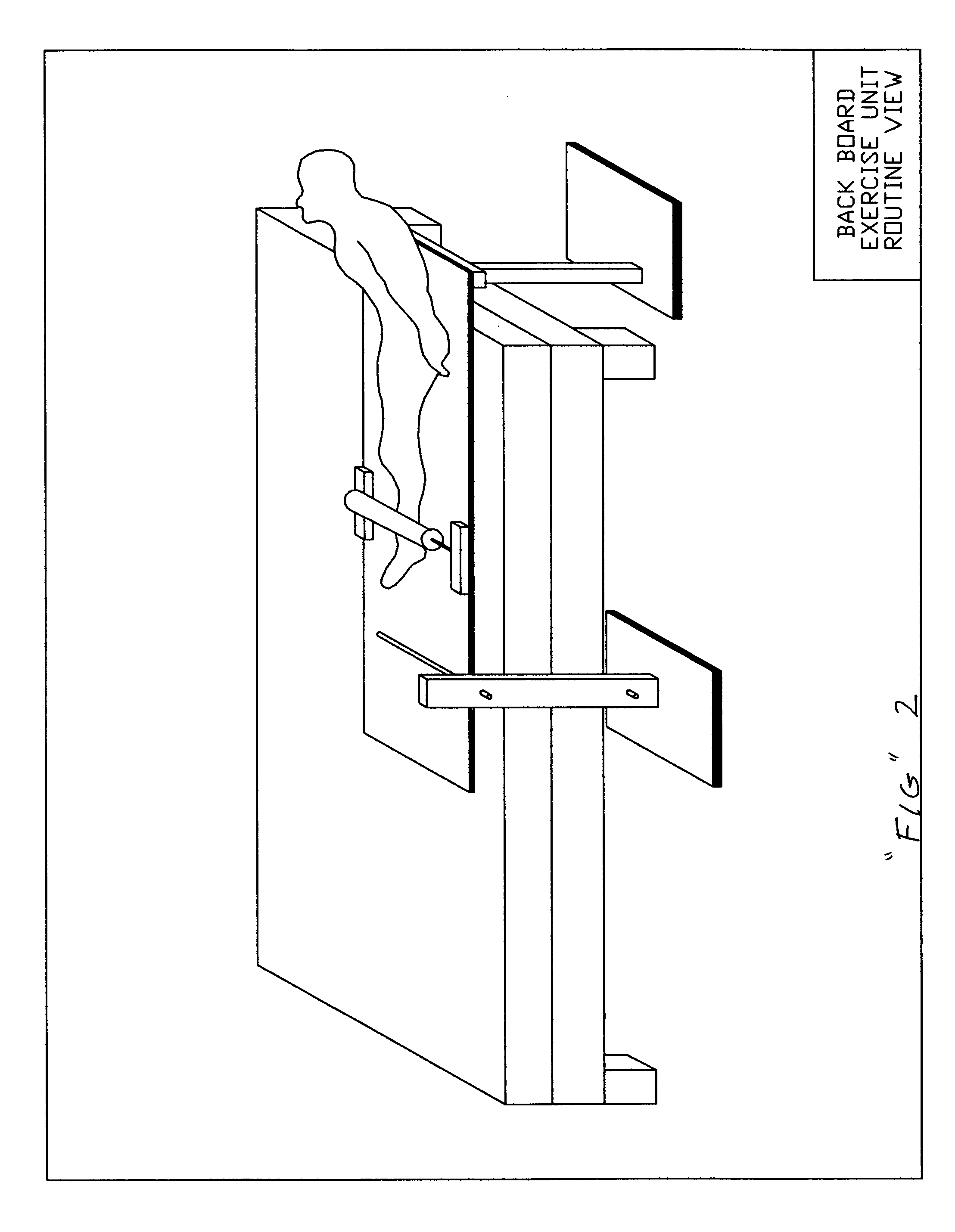
[0011]The invention consists of a rectangular board and two attachable upright support posts. The board which is rigid and light weight is mounted on a bed and serves as the platform from which exercises are performed. The board has a foam covered bar which serves to stabilize the lower extremities of the user as exercises are performed. The foam covered bar is adjustable in both the vertical and horizontal directions in order to accommodate users of various size. The rectangular board has two guide clamps on its top surface and a guide sleeve on its bottom surface.

[0012]The first support post has a rectangular base and a horizontal beam at its upper end. The first support post is positioned under the edge of the rectangular board at the foot of the bed. The horizontal beam has an aperture through which a first metal rod is passed in to the guide sleeve at the bottom of the rectangular board. The first metal rod serves to connect the first support post to the rectangular board. The ...


PUM


Abstract

The device is designed to enable the user to perform both abdominal strengthening and back muscle strengthening exercises on the top surface of a conventional bed. A conventional bed is defined as one with a semi-rigid mattress and a rigid frame.The device attaches and detaches to the said bed easily and provides the means to strengthen both the flexor and extensor muscles of the trunk with the added advantages of convenience and low cost. The device is a departure from the previous art as detailed in U.S. Pat. No. 6,890,289 Spinosa, May 10, 2005, in that it provides increased stability for both the bed and the user in the performance of said exercises.

Description

CROSS REFERENCES TO RELATED APPLICATIONS[0001]1.5106083Dec. 10, 1990Hall482 / 1452.4830367May 16, 1989Foran482 / 1403.4609193Sep. 2, 1986Paris482 / 1444.4522391Jun. 11, 1985Rundall482 / 405.4182511Jan. 8, 1980Camp482 / 1426.6231923Apr. 10, 2001Cameron482 / 1427.5776042Jul, 7, 1998Szabo482 / 1408.5871425Feb. 16, 1999Gvoich482 / 1409.6213923Mar. 1, 1999Cameron482 / 14010.5492520Feb. 1, 1996Brown482 / 14211.5725463Mar.1, 1998Colonello482 / 14012.5776042Jul. 7, 1998Szabo482 / 14013.1705745Mar. 1, 1929Anderson482 / 13314.4893813Jan. 16 1990Murray482 / 14515.5256126Oct. 1, 1993Grotstein482 / 13316.5346447Sep. 1, 1994Stearns482 / 14017.5441473Aug. 1, 1995Safani482 / 14018.4319747Mar. 1, 1982Rogers482 / 14519.6890289May 19, 2005Spinosa482 / 14020.3826490July 1974Mossman21.4515361May 1985Melillo et al22.4671257June 1987Kaiser et al23.4780919November 1988Hamson24.4893812January 1990Dawson et al25.4925184May 1990McJunkin et al26.5106083April 1992Hall27.5205804April 1993Hall28.5417636May 1995Havens30.5539741July 1996Barraclough et ...

Claims


Application Information

Patent Timeline
Patent Type & Authority Patents(United States)
IPC IPC(8): A63B26/00
CPCA63B23/0233A63B23/0211A63B21/1473A63B2021/1672A63B21/1672A63B21/4037
Inventor SPINOSA, JOSEPH
Owner SPINOSA JOSEPH
Why Eureka
Try Eureka