Locking member for an optical disk drive

Inactive Publication Date: 2007-01-16
LITE ON IT
View PDF8 Cites 5 Cited by
  • Summary
  • Abstract
  • Description
  • Claims
  • Application Information

AI Technical Summary

Benefits of technology

[0007]It is an object of the present invention to provide a locking member that can effectively withstand a large impact force for use in the optical disk drive.
[0009]In order to accomplish the objects of the present invention, the present invention provides a locking member for use in an optical disk drive. The locking member includes a rivet and a hollow element. A hole defined on the chassis of the optical disk drive is sized to receive the rivet, and the rivet extends through the hollow element. The rivet can be fixed on the chassis by riveting, and the locking member can absorb the large impact or shock. Alternatively, a screw thread can be integrally formed with the hollow element and the rivet. The rivet can be threaded through to engage with the hollow element to absorb the impact or shock without breakage or failure of the locking member.

Problems solved by technology

When the optical disk drive is being transported from one location to another, shock and other impact are inevitable.
Once the locking member 5 is bent or broken, the disk tray 2 cannot be locked inside the chassis 1, thereby rendering the optical disk drive unusable.

Method used


Image

  • Locking member for an optical disk drive
  • Locking member for an optical disk drive
  • Locking member for an optical disk drive

Examples


Embodiment Construction

[0021]The following detailed description is of the best presently contemplated modes of carrying out the invention. This description is not to be taken in a limiting sense, but is made merely for the purpose of illustrating general principles of embodiments of the invention. The scope of the invention is best defined by the appended claims.

[0022]Although the embodiments of the present invention are described below in connection with slim-type DVD-ROM drives, the present invention can be applied to all optical disk drives, including but not limited to CD-ROM drives, CD-RW drives, DVD-RAM drives, DVD-RW drives, DVD+RW drives, COMBO drives, car audio players, external drives, as well as all other optical media recorders and players.

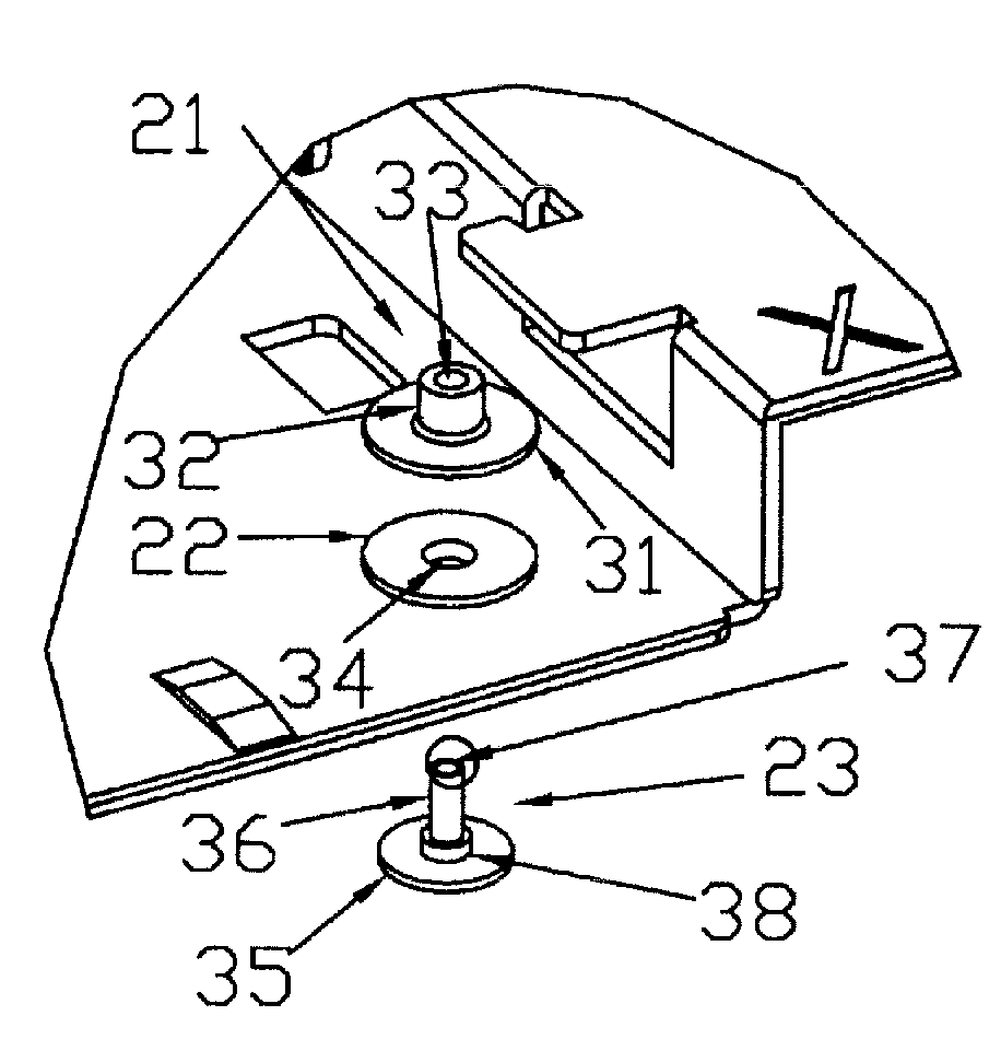
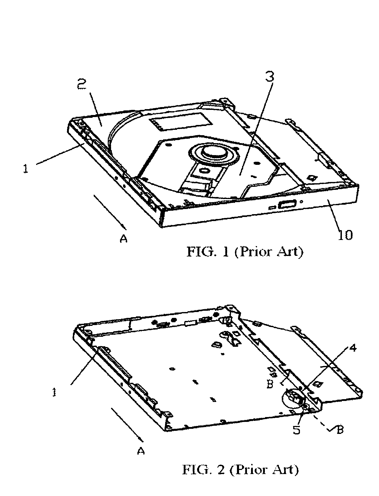
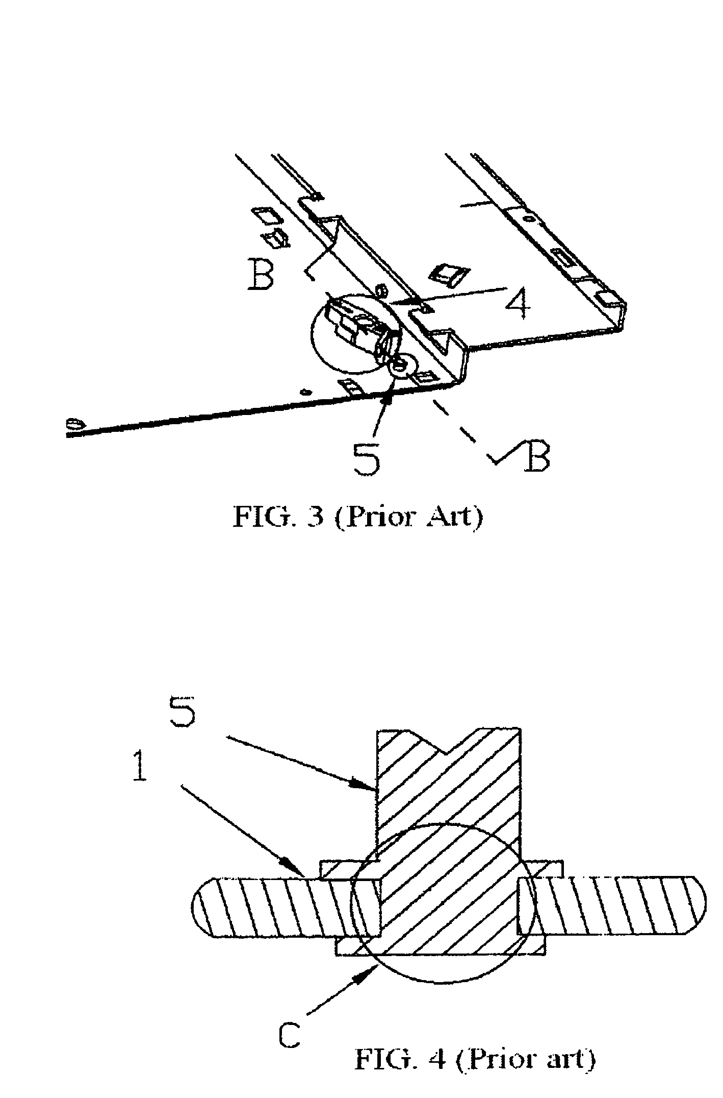
[0023]Referring to FIGS. 5 and 6, the optical disk drive of the present invention includes a chassis 11, a disk tray 12, and a playback unit 13 that can be the same as the a chassis 1, a disk tray 2 and a playback unit 3 of the conventional optical disk driv...


PUM


Abstract

A locking member for use in an optical disk drive includes a rivet and a hollow element. The hole defined on the chassis of the optical disk drive is sized to receive the rivet, and the rivet extends through the hollow element. The rivet can be fixed on the chassis by riveting, and the locking member can absorb a large impact or shock. Alternatively, screw threads can be integrally formed on the hollow element and the rivet. The rivet can be threaded through and engage with the hollow element to absorb the impact or shock without breakage or failure of the locking member.

Description

BACKGROUND OF INVENTION[0001]1. Field of the Invention[0002]The present invention relates to an optical disk drive, and in particular, to a locking member that is effective in resisting impact or shock that may be experienced by the optical disk drive.[0003]2. Description of the Prior Art[0004]Optical disk drives are becoming more popular in the market, having been considered standard equipment on personal computer for several years. Recently, slim-type optical disk drives, which can be used to conveniently load and unload optical disks, are being shipped with portable computers such as notebooks. In an attempt to reduce the cost and adapt to the limited space constraint within notebooks, the conventional motor for disk loading and unloading operations has been eliminated. FIGS. 1–4 illustrate a conventional disk drive and its loading and unloading device. The conventional disk drive has a chassis 1, a disk tray 2, a playback unit 3, a locking mechanism 4, and a locking member 5. Th...

Claims


Application Information

Patent Timeline
IPC IPC(8): G11B33/02G11B17/04G11B33/08
CPCG11B33/08G11B17/056
Inventor CHEN, JUNG-FU
Owner LITE ON IT
Why Eureka
Try Eureka