Thermoelectric Energy Conversion System

a technology of thermal energy conversion and thermal energy, applied in the field of geothermal energy systems, can solve the problems of avoiding the need for expensive corrosion suppression technology within, and achieve the effects of reducing the temperature of petroleum products, avoiding significant negative environmental impact, and reducing the cost of corrosion suppression technology

Inactive Publication Date: 2009-10-22
LOCKHEED MARTIN CORP
View PDF2 Cites 39 Cited by
  • Summary
  • Abstract
  • Description
  • Claims
  • Application Information

AI Technical Summary

Benefits of technology

[0014]In addition to generating electrical energy without significant negative environmental impact, in some of these embodiments the temperature of the petroleum product is advantageously reduced by virtue of the present invention. As a result, the crude oil and / or natural gas is made less corrosive. This obviates the need for using expensive corrosion suppression technology within the oil / gas production equipment and facility.

Problems solved by technology

This obviates the need for using expensive corrosion suppression technology within the oil / gas production equipment and facility.

Method used


Image

  • Thermoelectric Energy Conversion System
  • Thermoelectric Energy Conversion System
  • Thermoelectric Energy Conversion System

Examples


Embodiment Construction

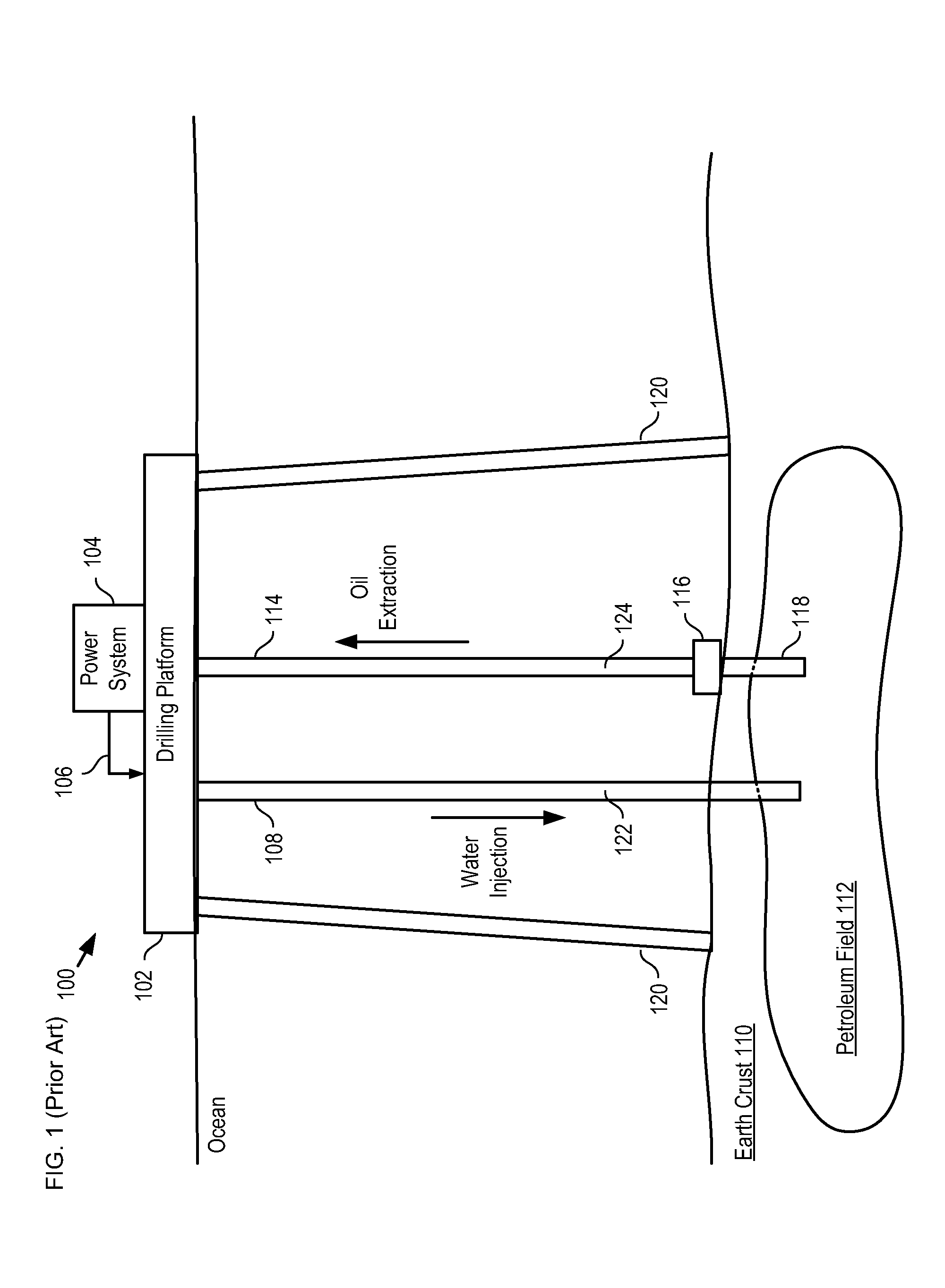
[0022]FIG. 1 depicts a representative ocean-based petroleum production system in accordance with the prior art. System 100 comprises tension-leg platform 102, power system 104, injection conduit 108, extraction conduit 114, and well head 116. System 100 is representative of floating installations that are widely used in deep-water areas to extract petroleum products, such as oil, natural gas, and the like, from sub-terranean petroleum fields.

[0023]Drilling platform 102 is a conventional “tension-leg” petroleum production facility. It normally comprises pumps, control equipment, drills, cranes, docking facilities, storage tanks, off-loading equipment, etc. Drilling platform is supported above the ocean floor by tension legs 120.

[0024]Power system 104 is an electrical energy generation system that provides electrical energy to drilling platform 102 on power cable 106. The generated electrical energy is used to run pumps, cranes, electrical systems, life support systems refrigeration, ...


PUM


Abstract

A system for generating electrical energy using a naturally occurring temperature difference is disclosed. The system provides electrical energy by thermally coupling a conduit that conveys hot material from a petroleum reserve and cold deep-level water to opposing sides of a thermoelectric element. The thermoelectric element generates electrical energy based on the temperature difference between these two surfaces.

Description

CROSS REFERENCE TO RELATED APPLICATIONS[0001]This case claims priority to: U.S. Provisional Patent Application Ser. No. 61 / 033,415, filed Mar. 3, 2008 (Attorney Docket: 711-136US); and U.S. Provisional Patent Application Ser. No. 61 / 042,185, filed Apr. 3, 2008 (Attorney Docket: 711-189US); each of which is incorporated by reference.[0002]If there are any contradictions or inconsistencies in language between this application and one or more of the cases that have been incorporated by reference that might affect the interpretation of the claims in this case, the claims in this case should be interpreted to be consistent with the language in this case.FIELD OF THE INVENTION[0003]The present invention relates to energy systems in general, and, more particularly, to geothermal energy systems.BACKGROUND OF THE INVENTION[0004]Off-shore operations platforms, such as petroleum production platforms, radar installations, and the like, require a local power source to enable operation of pumps, ...

Claims


Application Information

Patent Timeline
Patent Type & Authority Applications(United States)
IPC IPC(8): F03G7/05F01K7/38H01L35/00
CPCE21B41/0007E21B41/0085F01K13/00Y02E10/34F03G7/04F24J3/085Y02E10/14F01K27/00F24T10/20Y02E10/10Y02E10/30
Inventor RAPP, JOHN W.HOWARD, ROBERT JAMESNAGURNY, NICHOLAS J.LEVINGS, NATALIEGREER, LANCE
Owner LOCKHEED MARTIN CORP
Why Eureka
Try Eureka