Assembly for securing a wear member to an excavator

a wear member and wear technology, applied in mechanical machines/dredgers, dredgers, manufacturing tools, etc., can solve the problems of inability of operators, increased transverse loading of teeth, and inability to effectively guide cutterhead operators along paths, etc., to achieve easy positioning, accurate and quick manner

Inactive Publication Date: 2007-01-23
ESCO CORP
View PDF28 Cites 31 Cited by
  • Summary
  • Abstract
  • Description
  • Claims
  • Application Information

AI Technical Summary

Benefits of technology

This patent describes how to attach various components to an arm on a machine used for cutting materials like wood or metal. There are different parts of the arm that hold specific tools needed for this process. These parts have special markings called locator formations which help align and secure the tooling accurately. A separate attachment piece is also described that fits into these locators to make sure everything lines up perfectly when attaching new tools. Overall, this system makes it easier and more efficient to change out different tools quickly and ensures accuracy during the cutting process.

Problems solved by technology

The technical problem addressed in this patent text needs to be identified by a senior R&D personnel who has read it through.

Method used


Image

  • Assembly for securing a wear member to an excavator
  • Assembly for securing a wear member to an excavator
  • Assembly for securing a wear member to an excavator

Examples


Embodiment Construction

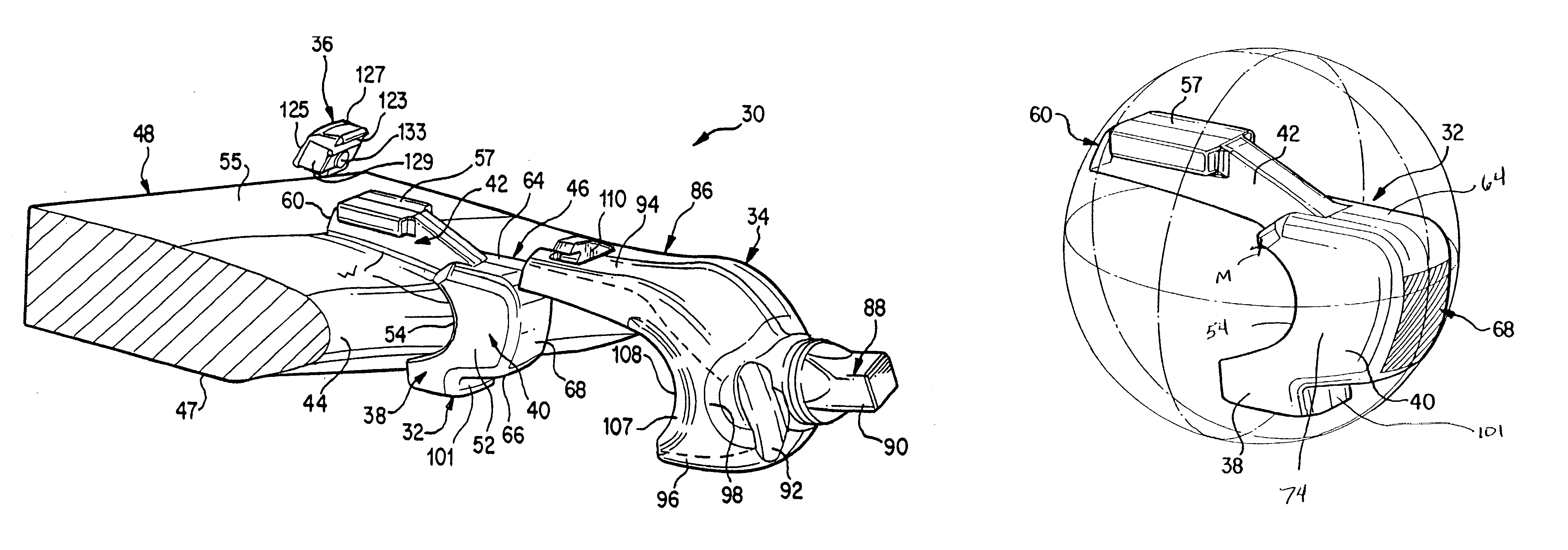
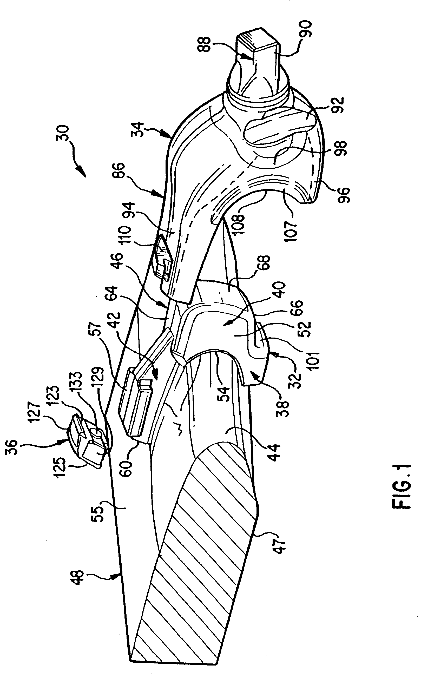
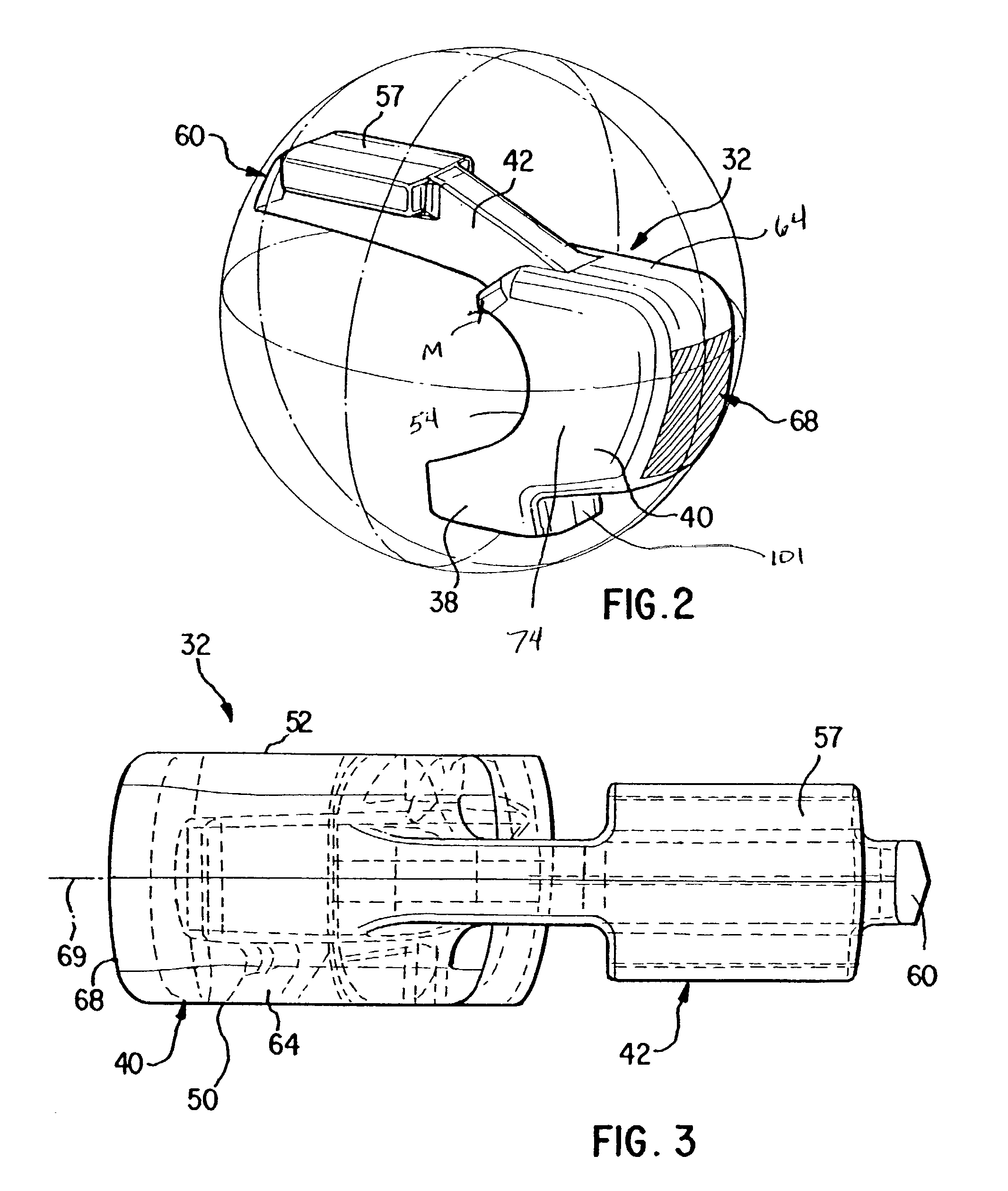
[0041]The present invention pertains to an assembly for securing a wear member to an excavator. The present invention is particularly suited for mounting a tooth on a dredge cutterhead because of the ability of the tooth in the preferred construction to better withstand heavy transverse loading typical of a dredging operation and dampen rattling of the parts. Nevertheless, a tooth in accordance with the present invention could be used with other excavators. Additionally, other wear members used in excavating equipment (e.g., shrouds) could be mounted using the present invention.

[0042]In accordance with the present invention, a tooth 30 includes a base or mount 32, an adapter 34, a point (not shown), and a lock 36 (FIG. 1). The tooth components will at times be described in relative terms, such as up and down, even though the operation of the dredging equipment will cause the teeth to assume many different orientations. These directions are used for explanation purposes only and shou...


PUM


Abstract

An assembly for mounting an excavating tooth particularly suited for a dredge cutterhead includes a base, an adapter, and a lock. The base includes a convex, curved bearing surface that abuts a concave, curved bearing surface on the adapter. The curved bearing surfaces are able to maintain substantially full contact with each other under transverse loading.

Description


Claims


Application Information

Patent Timeline
Owner ESCO CORP
Why Eureka
Try Eureka