Rake combining circuit and rake combining method

a technology of combining circuit and combining method, which is applied in the direction of diversity/multi-antenna system, wireless communication, wireless communication, etc., can solve the problems of inaccurate data receiving at expected signal component ratio, error in estimated value itself,

Active Publication Date: 2007-01-23
KAWASAKI MICROELECTRONICS
View PDF14 Cites 1 Cited by
  • Summary
  • Abstract
  • Description
  • Claims
  • Application Information

AI Technical Summary

Benefits of technology

[0007]An object of the invention is to solve the problems based on the prior art as described above and to provide a RAKE combining circuit and a RAKE combining method capable of giving a weight to the receive data of the respective paths in consideration of a phase error, receiving level deterioration and so forth.

Problems solved by technology

However, since a random noise component, an interfering component and the like may be contained in the receive data in a case that the respective demodulated receive data are given the weight on the basis of the power of the receive data, the receive data are not always combined accurately at an expected signal component ratio.
However, there is a possibility that the estimated value itself may have errors then.

Method used


Image

  • Rake combining circuit and rake combining method
  • Rake combining circuit and rake combining method
  • Rake combining circuit and rake combining method

Examples


Embodiment Construction

[0040]A detailed description will now be given of a RAKE combining circuit and a RAKE combining method of the invention based on the preferred embodiment shown in the accompanying drawings.

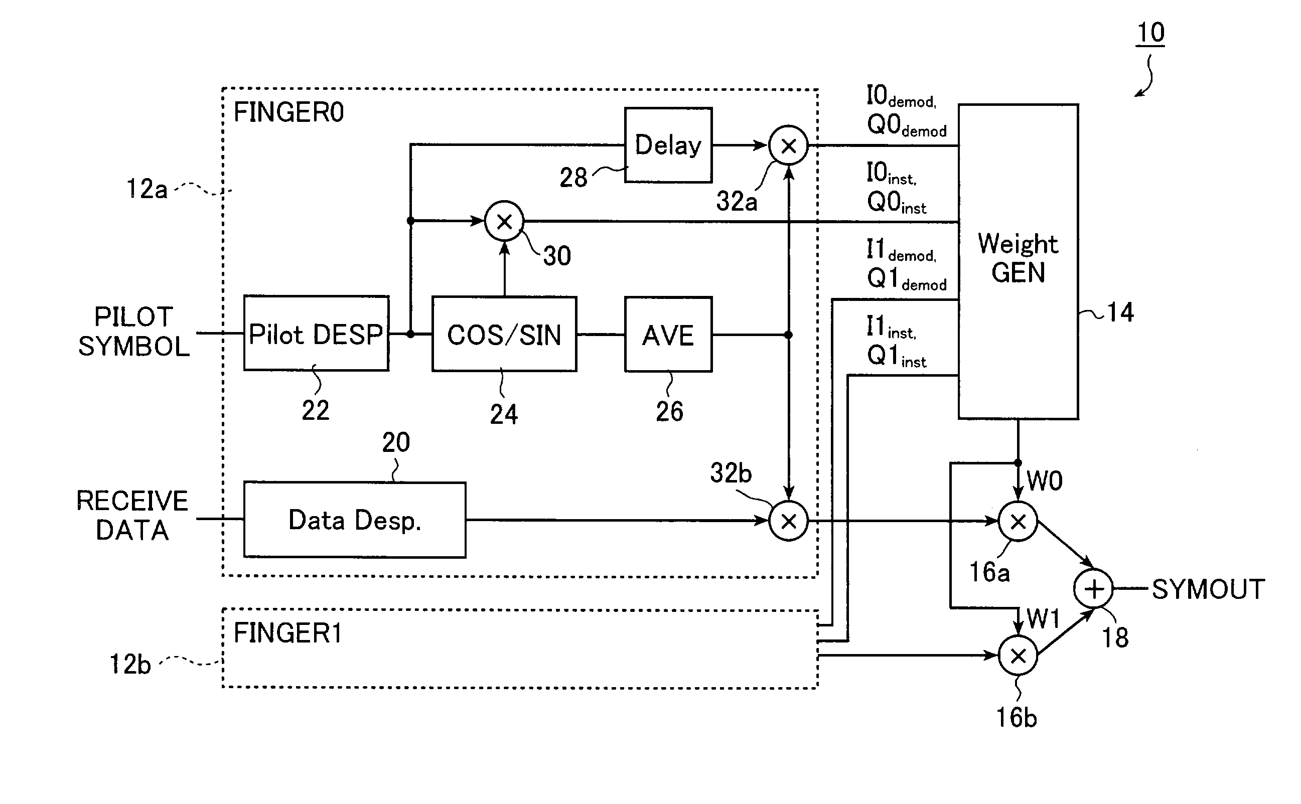
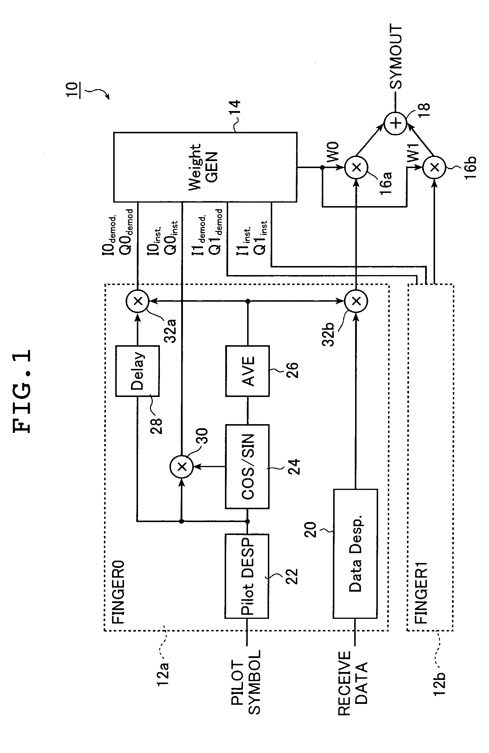
[0041]FIG. 1 is a schematic diagram of one embodiment of a RAKE combining circuit of the invention to which a RAKE combining method of the invention is applied.

[0042]The RAKE combining circuit 10 shown in FIG. 1 gives a weight to two receive data to combine based on pilot symbols. The RAKE combining circuit 10 has two fingers (FINGER 0 and FINGER 1) 12a and 12b, a weight factor generation circuit (Weight GEN) 14, two multipliers 16a and 16b arranged corresponding to the fingers 12a and 12b, and an adder 18.

[0043]In the RAKE combining circuit 10 shown in FIG. 1, according to a RAKE combining method of the invention, a plurality of kinds of pilot symbols which have a known bit pattern and a known phase together with data series as communication information are received and a deviation between the kn...


PUM


Abstract

Not only an instantaneous pilot symbol value resulting from correcting a phase of one demodulated pilot symbol in response to phase deviation of the one pilot symbol but also a pilot symbol value resulting from correcting a phase of the same pilot symbol corresponding to the instantaneous pilot symbol value in response to averaged phase deviation of a plurality of demodulated receive pilot symbols is calculated. Further, weight factors are generated on the basis of a difference between the instantaneous pilot symbol value and the pilot symbol value, and the respective demodulated receive data is weighted by using the weight factors to combine the receive data.

Description

TECHNICAL FIELD[0001]The present invention relates to a RAKE combining circuit for use in a mobile communication system utilizing a spread spectrum system and to a RAKE combining method.BACKGROUND ART[0002]In a mobile communication system that utilizes a spread spectrum system, there has been used a technique called a RAKE receiving system for improving communication quality. In this receiving system, a plurality of data received via different communication paths are demodulated in circuits called fingers and these demodulated data are combined. In the RAKE receiving system, a weight is added to each of output signals from the fingers in some way when the demodulated data are combined. Generally, the weighting is often carried out on the basis of power of the receive data.[0003]FIG. 6 shows an example of a schematic diagram of a conventional RAKE combining circuit.[0004]The RAKE combining circuit 50 shown in FIG. 6 has three fingers (Finger 0, Finger 1 and Finger 2) 52a, 52b and 52c...

Claims


Application Information

Patent Timeline
Patent Type & Authority Patents(United States)
IPC IPC(8): H04B7/216H04Q7/28H04B1/00H04B7/208H04B1/707H04B1/712H04B7/08
CPCH04B1/707H04B1/712H04B2201/70701
Inventor KONDO, HISASHI
Owner KAWASAKI MICROELECTRONICS
Why Eureka
Try Eureka